Knee joint radio-frequency (RF) coil in horizontal-field magnetic resonance system

A radio frequency coil and magnetic resonance technology, applied in magnetic resonance measurement and other directions, can solve the problems of reduced selectivity and effect of parallel imaging, large coupling, high price, etc., and achieve flexible PAT selectivity, high-quality PAT effect, and reliable connection quality. Effect

Inactive Publication Date: 2012-10-24
SUZHOU MEDCOIL HEALTHCARE
View PDF5 Cites 7 Cited by
  • Summary
  • Abstract
  • Description
  • Claims
  • Application Information

AI Technical Summary

Problems solved by technology

But it also has three obvious defects: 1. When the upper and lower parts are made into a separable structure, the signals of at least two channels in the upper part need to be connected to the lower part with RF coaxial connectors, which are used in magnetic resonance systems. The non-magnetic RF coaxial connector is relatively expensive, and it is easy to be damaged when it is used to connect the upper and lower parts; 2. Among the different antenna units, only the adjacent or sub-adjacent antenna units can have good detachment. Coupling effect, because between adjacent antenna elements (such as between Ch2 and Ch1, or between Ch2 and Ch3), partial overlap can be used to decouple; and between adjacent antenna elements such as Ch2 and Ch8, or between Ch2 and Ch4), can use capacitive or inductive decoupling
However, it is difficult to take decoupling measures between antenna elements that are farther apart (such as between Ch2 and Ch7, Ch6 or Ch5), which makes the coupling between each antenna element relatively large and reduces the signal-to-noise ratio of the entire coil 3. Because its 8 antenna units are arranged in the direction of the ring, so that its parallel imaging direction can only have a corresponding acceleration factor in the direction of the ring, so the selectivity and effect of parallel imaging are significantly reduced

Method used


Image

  • Knee joint radio-frequency (RF) coil in horizontal-field magnetic resonance system
  • Knee joint radio-frequency (RF) coil in horizontal-field magnetic resonance system
  • Knee joint radio-frequency (RF) coil in horizontal-field magnetic resonance system

Examples


Embodiment

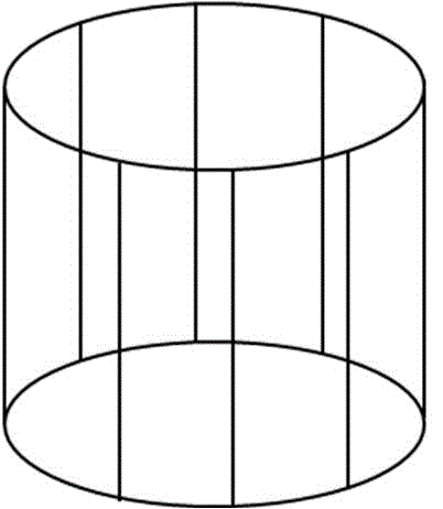
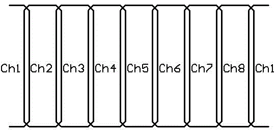
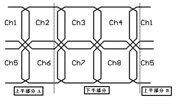
[0024] The radio frequency coil of the knee joint in a kind of horizontal field magnetic resonance system of the present embodiment, such as image 3 As shown, it includes 8 antenna units. The antenna unit is divided into a detachable upper part (composed of upper part A and upper part B) and a lower part from which the upper part can be removed and placed on the patient's bed. Then cover the top half. The upper half and the lower half are 4 antenna units respectively, and the lower half is the part sandwiched between the left and right dashed lines, including antenna units ch3, ch4, ch7, ch8; the upper half includes antenna units ch1, ch2, ch5, ch6; the four antenna elements ch1, ch2, ch5, and ch6 in the upper half have a side in the lower half. The antenna units are arranged in a 2×4 manner, and the axial direction is divided into 2 sections, and each section has 4 antenna units. Adjacent antenna elements partially overlap. The upper half and the lower half form a cylindr...


PUM


Abstract

The invention discloses a knee joint radio-frequency (RF) coil in a horizontal-field magnetic resonance system. The knee joint RF coil comprises a plurality of antenna units, wherein the number of the antenna units is greater than two, the antenna units are divided into an upper half part and a lower half part which can be separated from each other, and adjacent antenna units are partially overlapped. The knee joint RF coil in the horizontal-field magnetic resonance system, disclosed by the invention, has the advantages that the manner of connection between the upper half part and the lower half part is excellent, the quality of connection is more reliable, the decoupling effect, the sensitivity (signal-to-noise ratio) and the uniformity among the antenna units of the coil are improved, the PAT (Parallel Acquisition Technique) selectivity is flexible, and the PAT effect is excellent.

Description

technical field [0001] The invention belongs to the field of magnetic resonance imaging, in particular to a knee joint radio frequency coil in a horizontal field magnetic resonance system. Background technique [0002] Magnetic resonance system is a high-end medical imaging equipment, which can be divided into horizontal field magnetic resonance system and vertical field magnetic resonance system according to the magnetic field direction of the main magnet. A horizontal field system means that the direction of the magnetic field of the magnet is parallel to the torso of the person, pointing from the brain to the soles of the feet or vice versa. The vertical field system means that the direction of the magnetic field of the magnet is perpendicular to the direction of the torso of the person, such as from the front of the person to the back. The magnetic field direction of the magnet is the most important reference for designing the RF coil, because the antenna unit in the co...

Claims


Application Information

Patent Timeline
Patent Type & Authority Applications(China)
IPC IPC(8): G01R33/36
Inventor 刘佩琴俞涛朱华彬
Owner SUZHOU MEDCOIL HEALTHCARE
Why Eureka
Try Eureka