Pull force self-coordination type multi-line suspension plate node structure

A self-coordinated, node-structured technology, applied in the direction of cable suspension devices, can solve the problems of increasing the safety of support points, increasing costs, etc., and achieves the effects of simple structure, convenient installation, and reduced distortion

Inactive Publication Date: 2012-10-24
CHINA ENERGY ENG GRP GUANGDONG ELECTRIC POWER DESIGN INST CO LTD
View PDF5 Cites 0 Cited by
  • Summary
  • Abstract
  • Description
  • Claims
  • Application Information

AI Technical Summary

Problems solved by technology

This kind of hanging plate structure has the following disadvantages: because the hanging plate is fixedly connected to the support frame, the guiding tension in different directions generates moments relative to the nodes (fixed connection points between the hanging plate and the support frame), which easily distorts the support point of the support frame On the one hand, it increases the unsafety of the support point, on the other hand, it needs to increase the rigidity of the support frame, thus increasing the cost

Method used


Image

  • Pull force self-coordination type multi-line suspension plate node structure
  • Pull force self-coordination type multi-line suspension plate node structure
  • Pull force self-coordination type multi-line suspension plate node structure

Examples


specific Embodiment 1

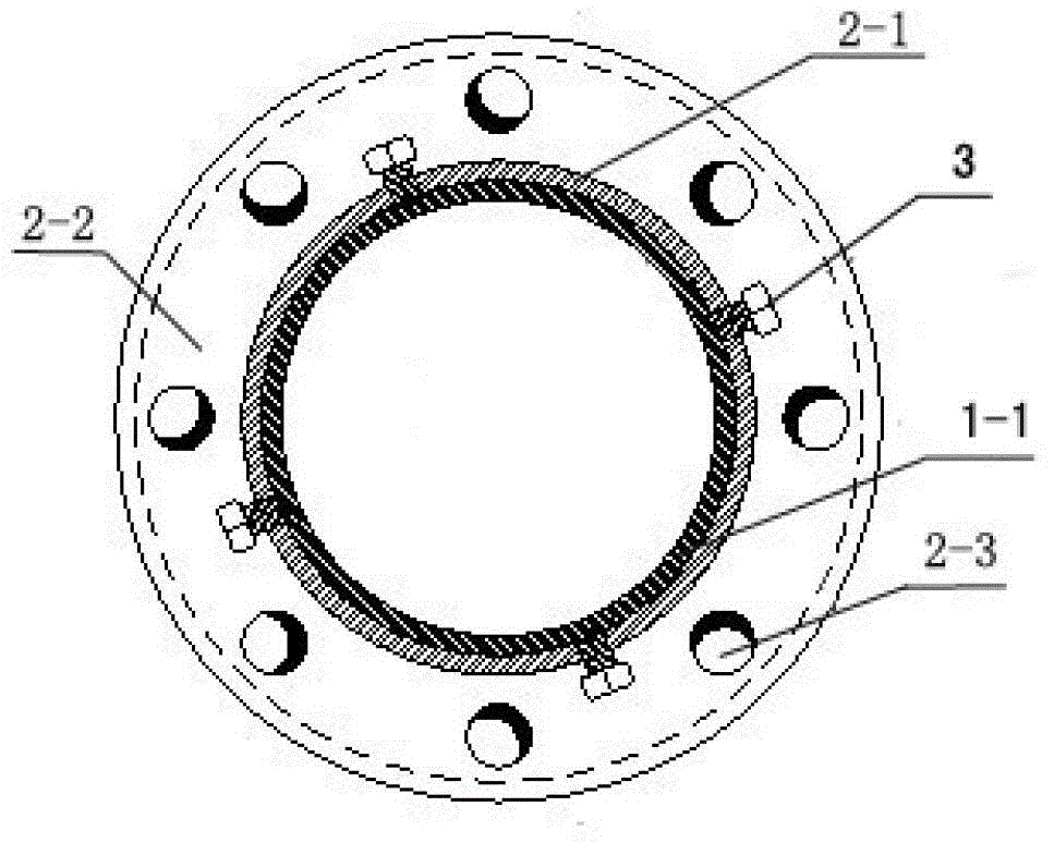
[0025] Such as Figure 3 to Figure 8 As shown, this embodiment includes a fixed part 1 and a movable part 2, the fixed part is fixed by pre-embedding, bolts or welding, and the fixed part has a protruding part 1-1, which is cylindrical or cylindrical, formed Hanging wire support structure; the movable part 2 is sleeved on the protruding part 1-1 of the fixed part to form a relative rotating connection structure, and several hanging wire units are extended from the outer wall of the movable part 2, and the several hanging wire units are scattered The outer wall of the movable part 2 is provided with a plurality of radial screw through holes, and the locking bolt 3 will connect the movable part 2 with the fixed part 1 through the screw through holes.

[0026] In this example:

[0027] The movable part 2 is composed of a concentric cylinder 2-1 and a ring 2-2. The cylinder 2-1 is sleeved on the protruding part 1-1 of the fixed part, and its size and shape coincide with the protr...

specific Embodiment 2

[0034] The characteristics of other embodiments of the present invention are: the same fixed part 1 can be socketed with 1~3 movable parts 2, so as to meet more wires and more height requirements.

specific Embodiment 3

[0035] The characteristics of other embodiments of the present invention are: the plurality of hanging wire holes 2-3 can be one, two, three, four, five, six, seven, eight, nine or more than ten , all the other structures and working principles are the same as those in Embodiment 1.


PUM


Abstract

The invention discloses a pull force self-coordination type multi-line suspension plate node structure. The pull force self-coordination type multi-line suspension plate node structure comprises a fixed part and a movable part and is characterized in that the fixed part is fixed to a lower part structure through embedding, bolts or welding and is provided with a projection part; the projection part is in a cylinder shape or in a barrel shape and forms a suspension line supporting structure; the movable part is sleeved onto the projection part of the fixed part and forms a relatively rotatable connection structure; a plurality of suspension line units extend from the outer side wall of the movable part and are radially arranged and located on the same plane; a plurality of radial screwing through holes are formed on the outer side wall of the movable part; and the movable part is connected with the fixed part by a locking bolt through the screwing through holes after suspension lines are mounted. The pull force self-coordination type multi-line suspension plate node structure is simple in structure; and with the adoption of the pull force self-coordination type multi-line suspension plate node structure, the resultant force of a plurality of pull lines finally acting on the fixed part is minimal, the torque effect cannot be generated, and a supporting frame is more stable.

Description

technical field [0001] The invention relates to a tension self-coordinating multi-wire hanging board node structure, which is suitable for hanging boards used in overhead power transmission lines or substations. It belongs to the technical field of electric power transmission equipment. Background technique [0002] At present, hanging boards are used in overhead transmission lines in electric power engineering. The hanging boards usually use a fixed steel plate. Because the angles and positions of the hanging wires are different, it is necessary to open holes in different positions and sizes on the hanging boards as wires. Hanging point, it is convenient to connect the wire to the hanging board, and it may be necessary to connect hanging wires in different directions at the same node position, especially when it is used to hang the lightning protection line, the hanging board node on the top of the lightning protection tower needs to hang multiple pieces Lightning conducto...

Claims


Application Information

Patent Timeline
Patent Type & Authority Applications(China)
IPC IPC(8): H02G7/05
Inventor 杨雪平池代波韦文兵曾程黄汉昌
Owner CHINA ENERGY ENG GRP GUANGDONG ELECTRIC POWER DESIGN INST CO LTD
Why Eureka
Try Eureka