

Elastic network interface realization method and system
A technology of elastic network and implementation method, which is applied in the field of communication, can solve problems such as the inability to guarantee the normal transmission of traffic, achieve the effect of improving reliability and link utilization, and ensuring normal operation
- Summary
- Abstract
- Description
- Claims
- Application Information
AI Technical Summary
Problems solved by technology
Method used
Image

Examples
Embodiment 1
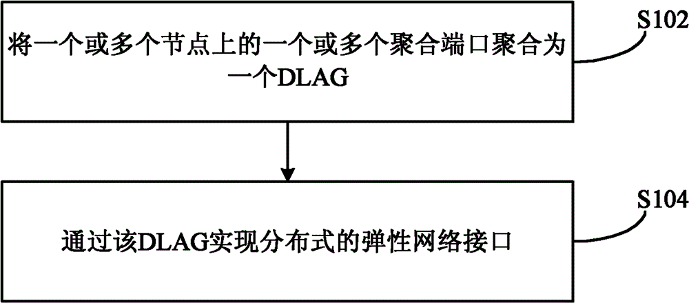
[0046] This embodiment provides a method for implementing and protecting an elastic network interface, see figure 1 , the method includes the following steps:
[0047] Step S102, aggregating one or more aggregation ports on one or more nodes into a DLAG;
[0048] One or more nodes here may be located in the same network, and all are connected to one or more nodes of another network. It can also be located in a different network or within a network.
[0049] When the one or more nodes are located in the same network and are all connected to one or more nodes of another network, the aggregated DLAG is preferably a distributed elastic network interconnection interface, and the elastic network interconnection The connection port is used to transmit the traffic inside the network to the outside of the network, or to transmit the traffic outside the network to the inside of the network, and realize the protection of the traffic between the inside and outside of the network.
[00...
example 1
[0096] Such as Figure 5 In the network connection topology diagram shown, nodes A and B have their own node IDs (node id), which are 001 and 002 respectively, and also have their own node priorities (node priority), which are 0 and 1 respectively. Similarly, nodes C and D have their own node ids, which are 003 and 004 respectively, and their own node priorities, which are 0 and 1 respectively. It is hoped that through LICP and LACP, a' of node A and b' of node B can form a distributed link aggregation group DLAG; c' of node C and d' of node D can also form a distributed link aggregation group Group DLAG. From a macro point of view, although the link between A and C and the link between B and D are on different nodes, they work in an aggregation group, and traffic can be transmitted through this aggregation group to achieve traffic control. protection and load sharing.
[0097] b' and a' notify each other of their own system information (i.e. the system parameters in th...
example 2
[0107] Such as Figure 10 In the network connection topology diagram shown, there are two edge nodes in the network on each side, and the network 11 is connected to the nodes C and D of the network 22 through nodes A and B. There is a full connection between nodes A, B, C, and D, that is, A is connected to C and D, and B is also connected to C and D. When a' and b' are regarded as a DLAG, c' and d' are viewed as When it is a DLAG, there are four aggregated links in this DLAG, and traffic protection and load sharing are realized through these aggregated links.
[0108] The aggregation process of this example is similar to Example 1. b' and a' notify each other of their system information through the LICP protocol, such as system id, system priority, key and other information. The format can be as follows Figure 6 , Figure 7 , Figure 9 As shown, when these values are the same, it is possible for these nodes to aggregate into a DLAG.
[0109] Therefore, b' notifies a' of...
PUM
 Abstract
Description
Claims
Application Information