
Passive optical network and its optical network unit optical module

A passive optical network and optical module technology, which is applied in the direction of star electromagnetic network, electromagnetic network arrangement, optical fiber transmission, etc., can solve the problems that the optical network cannot provide enough upstream channel bandwidth and cannot meet business needs, so as to improve bandwidth, The effect of improving the uplink bandwidth and ensuring stability

Active Publication Date: 2015-09-30
HISENSE BROADBAND MULTIMEDIA TECH
View PDF5 Cites 0 Cited by
  • Summary
  • Abstract
  • Description
  • Claims
  • Application Information

AI Technical Summary

Problems solved by technology

However, the current WDM PON technology is only limited wavelength multiplexing based on CWDM (full-wave 16 wavelengths, generally only 4 wavelengths in the 1320 band are used), even if DWDM technology is introduced, it is limited by the externally modulated laser Due to the limitations of spectral width and wavelength temperature drift, the channel spacing is only controlled at 200GHz intervals (45 channels in C-band)
[0006] Therefore, the existing optical network cannot provide sufficient upstream channel bandwidth to meet the growing business needs

Method used


Image

  • Passive optical network and its optical network unit optical module
  • Passive optical network and its optical network unit optical module
  • Passive optical network and its optical network unit optical module

Examples


Embodiment Construction

[0058] In order to make the object, technical solution and advantages of the present invention clearer, the present invention will be described in further detail below with reference to the accompanying drawings and preferred embodiments. However, it should be noted that many of the details listed in the specification are only for readers to have a thorough understanding of one or more aspects of the present invention, and these aspects of the present invention can be implemented even without these specific details.

[0059] As used herein, terms such as "module" and "system" are intended to include computer-related entities such as, but not limited to, hardware, firmware, a combination of hardware and software, software, or software in execution. For example, a module may be, but is not limited to being limited to being, a process running on a processor, a processor, an object, an executable, a thread of execution, a program, and / or a computer.

[0060] In the passive optical...


PUM


Abstract

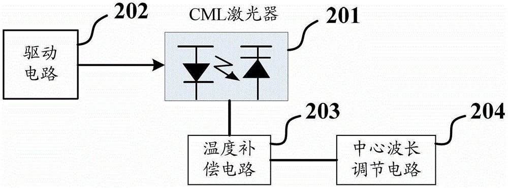
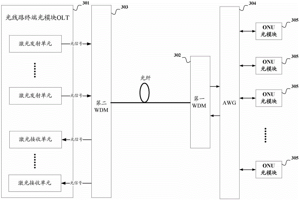
A passive optical network and an optical module of an optical network unit thereof are disclosed. The optical network comprises an Optical Line Terminal (OLT), a first Wavelength Division Multiplexing (WDM), a second WDM and a plurality of optical modules of Optical Network Units (ONU), wherein a laser emission unit in the optical module of ONU comprises a Chirp Managed Laser (CML) and a driving circuit thereof. The driving circuit of the laser emission unit is used for receiving electrical signals sent by an ONU system device and driving the CML to emit optical signals with a specific wavelength according to the received electrical signals. The wavelengths of optical signals emitted by different optical modules of ONU are different. The OLT comprises a plurality of laser receiving units which are respectively used for receiving the optical signal with each wavelength, converting the received optical signals into the electrical signals and then sending them to a switch. The CML adopted in the optical module of ONU has better spectrum characteristic, accordingly reducing channel interval and achieving the purposes of supplying more uplink channels and increasing system bandwidth.

Description

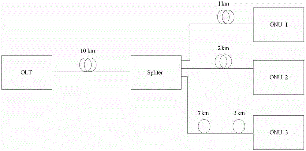
technical field [0001] The invention relates to optical fiber communication technology, in particular to a passive optical network and an optical network unit optical module thereof. Background technique [0002] in such as figure 1 In the passive optical network shown, the OLT (Optical Line Terminator, optical line terminal) is usually set in the central office of the access network system of the optical fiber communication system, and the OLT is responsible for converting the electrical signal data in the switch into optical signal data and sending it out , and receive the optical signal transmitted from the outside, convert it into an electrical signal and send it to the switch. The OLT is connected to the ONU (optical net unit, optical network unit) optical module through the ODN (optical feeder network). The ONU optical module is usually set at the central office, that is, the user end or the building; port, if the light intensity of the input port is 1, then the ligh...

Claims


Application Information

Patent Timeline
Patent Type & Authority Patents(China)
IPC IPC(8): H04Q11/00H04B10/25H04B10/50
CPCH04J14/025H04B10/272H04J14/0246H04J14/0282
Inventor 薛登山赵其圣何鹏
Owner HISENSE BROADBAND MULTIMEDIA TECH
Learn More