
Planter and method of operating a planter with individual meter control

A technology of seed metering and seeding machine, which is applied in the directions of seeding machine, seeder parts, agricultural machinery and implements, etc., can solve problems such as waste

Active Publication Date: 2012-10-31
DEERE & CO
View PDF12 Cites 13 Cited by
  • Summary
  • Abstract
  • Description
  • Claims
  • Application Information

AI Technical Summary

Problems solved by technology

Mechanical or hydromechanical actuated systems may be attributed to these wastes

Method used


Image

  • Planter and method of operating a planter with individual meter control
  • Planter and method of operating a planter with individual meter control
  • Planter and method of operating a planter with individual meter control

Examples


Embodiment Construction

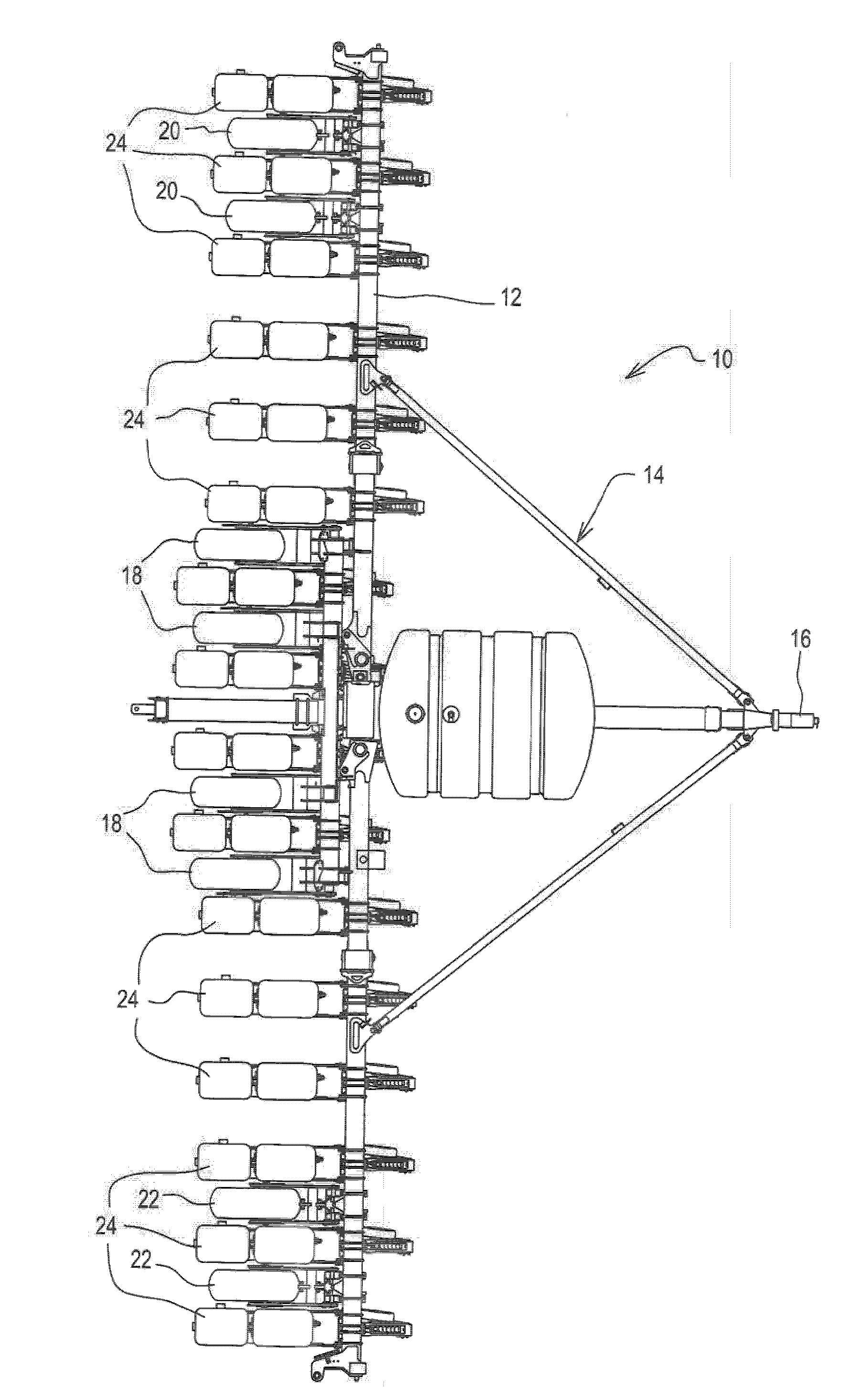
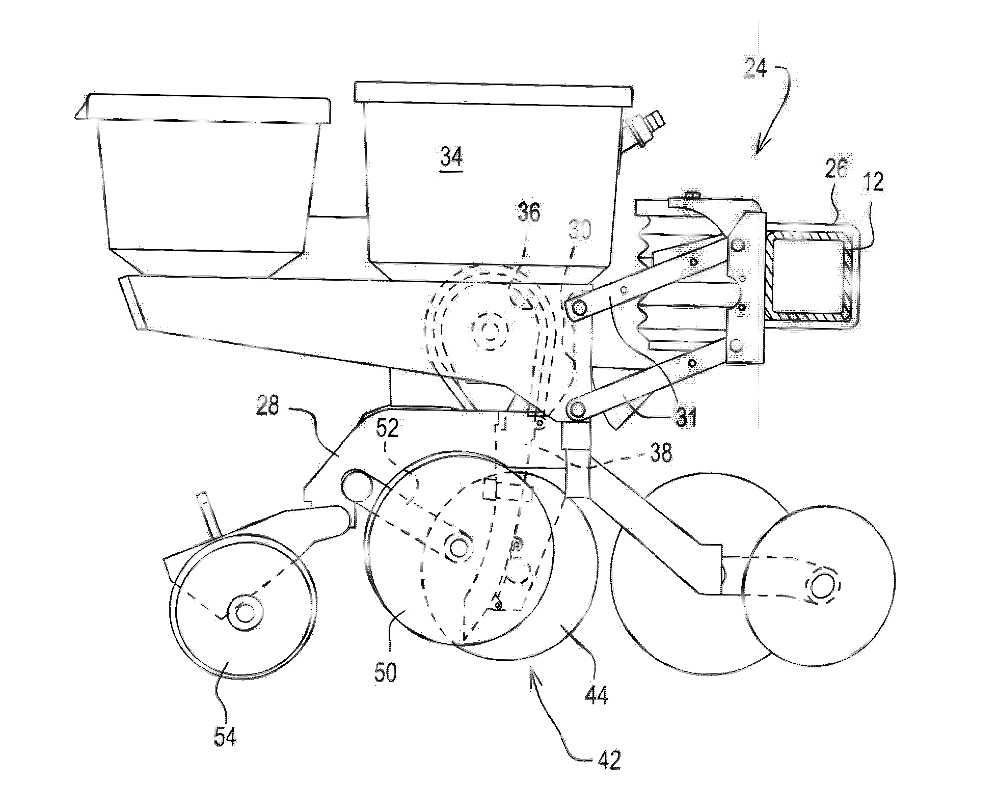
[0016] refer to figure 1 , the planting machine is shown in the form of a row crop planter 10 . The drill 10 includes an implement frame 12 that is part of a drill frame 14 . The frame includes a tongue 18 by which the planter is connected to a tractor (not shown). Three sets of ground engaging wheels support the planter frame 14 . The center set has four wheels 18 , while the left set has two wheels 20 and the right set has two wheels 22 . A plurality of planter row units 24 are mounted to the implement frame. for a given seeder. Row cells 24 are typically, but need not be, identical. exist figure 2 The row unit 24 is shown in more detail in . Row unit 24 is mounted to implement frame 12 by U-bolts 26 . The row unit 24 is provided with a central frame member 28 having a pair of upwardly extending arms 30 at its front end. The arm 30 is connected to a parallel link 31 for mounting the row unit 24 to the implement frame 12 for relative movement up and down between the...


PUM


Abstract

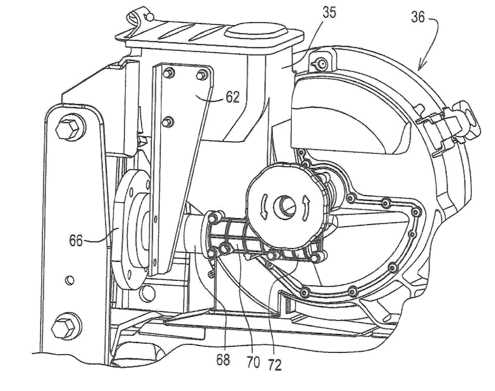
A planter is described which utilizes individual seed meter motor drives at each row unit. motor controllers control each seed meter drive motor. Each individual row seed meter can be individually started, stopped and operated at a unique rate. Prior to planting, the meters can be operated to fill the meters and ensure that the meters are primed and ready to start dropping seed as soon as the planter begins operation to plant seed. When a seed delivery system is used with each meter to move seed from the meter to the soil, the delivery system is also primed with seed before operation of the planter.

Description

technical field [0001] The present invention relates to a seeding machine, such as a planter, and a method of operating a seeding machine. Background technique [0002] Agricultural seeders are designed to sow crops such as corn, soybeans, cotton, peanuts and other crops. Modern planters are typically 12 or more rows across width. The overall width of these planters requires that they have a flexible frame for following ground contours and folding for narrow delivery widths. Among them, the row unit on the seeder usually includes a seed meter. The seed meter performs a centering function in the precise placement of the seed in the ground. Precise and accurate seed placement is a factor in crop yield and, in turn, in farm profitability. [0003] Seed meters are usually driven by mechanical or hydro-mechanical systems and may include many complex drive chains and drive shafts to transmit power from a central power source to individual row units. The flexible and folding c...

Claims


Application Information

Patent Timeline
IPC IPC(8): A01C7/00A01C7/20
CPCA01C7/10A01C7/105A01C7/046A01C7/20A01B79/005A01C7/08A01C7/102A01C19/02
Inventor 詹姆斯・R・彼得森卡尔・休伯纳哥迈克尔・E・弗莱泽戴夫・J・瑞兰达
Owner DEERE & CO
Learn More