
Digitization panorama dental X line imager

An imager and dental technology, applied in the field of X-ray imager, can solve the problems of complex operation, large radiation dose, chemical pollution, etc., and achieve the effect of no need for laser scanner, small X-ray exposure dose, and large exposure latitude

Inactive Publication Date: 2012-10-31
BEIJING UNIV OF TECH
View PDF8 Cites 5 Cited by
  • Summary
  • Abstract
  • Description
  • Claims
  • Application Information

AI Technical Summary

Problems solved by technology

The film cassette type X-ray panoramic machine is the most traditional imaging method. It consists of an intensifying screen, a photosensitive film and a cassette. It needs to go through the steps of developing, fixing, washing and drying to obtain images. The operation is complicated and has certain chemical pollution; The IP plate X-ray panoramic machine is an indirect imaging method, which needs to scan the IP plate with a laser scanner to obtain a digital image. Although it does not need to be processed to improve the efficiency, the operation is still complicated, time-consuming, and the radiation dose is large; charge-coupled The device-type X-ray panoramic machine can directly convert the received X-rays into image data, without chemical processing in the darkroom, with fast imaging speed, higher imaging resolution, and smaller radiation dose
[0003] At present, domestic dental panoramic X-ray imaging equipment is in the stage of upgrading, and digital imaging is the development trend. However, there is no domestic manufacturer that directly produces digital dental panoramic X-ray imaging equipment. Large hospitals mainly adopt foreign imports. , while most small and medium-sized hospitals still use traditional film cassette X-ray panoramic machines or IP plate X-ray panoramic machines

Method used


Image

  • Digitization panorama dental X line imager

Examples


Embodiment Construction

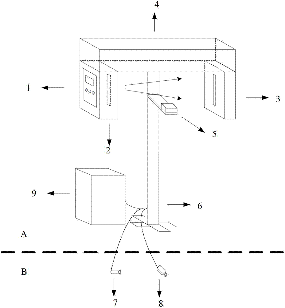
[0012] The invention provides a digital panoramic dental X-ray imager, which combines figure 1 For further clarification:

[0013] The digital panoramic dental X-ray imager provided by the present invention includes an X-ray exposure setting panel 1, an X-ray generator 2, an X-ray receiver 3, a C-arm 4, a storage platform 5, a support device 6, and an X-ray exposure handbook 7 , USB interface 8 and power supply 9 . The structure diagram of the digital panoramic dental X-ray imager is as follows: figure 1 shown. Set the X-ray exposure parameters and exposure time through the X-ray exposure setting panel 1, and control the X-ray generator 2 to generate X-rays of different doses; the X-rays are received by the X-ray receiver 3 through the storage platform 5, and the storage platform 5 is located at X Between the line generator 2 and the X-ray receiver 3; the X-ray receiver 3 outputs digital signals after receiving the X-rays, and uploads them to the computer through the USB in...


PUM


Abstract

The invention discloses a digitization panorama dental X line imager used for generating a digital image comprising full mouth teeth and a periodontium. The digitization panorama dental X line imager comprises an X line exposure setting panel, an X line generator, an X line receiver, a C-shaped arm, a storage platform, a support device, an X line exposure script, a USB(power supply) interface and a power supply, wherein the X line exposure setting panel is used for setting an X line exposure parameter, and the X line generator is controlled to generate an X line; the X line passes through the storage platform so as to be received by the X line generator, and the X line generator receives the X line and then outputs a digital signal which is uploaded to a computer through the USB interface; the two ends of the C-shaped arm are respectively connected with the X line generator and the X line receiver, and the X line exposure setting panel and the X line generator are arranged on the same side of the C-shaped arm; the support device is connected with the C-shaped arm, the storage platform, the X line exposure script, the USB interface and the power supply; and the power supply provides the required voltage for the whole X line imager. The digitization panorama dental X line imager provided by the invention has the advantages of being pollution-free, small in radiation dosage, high in imaging speed, simple in operation, and rich in digital image level.

Description

technical field [0001] The invention relates to an X-ray imager, in particular to a digital panoramic dental X-ray imager. Background technique [0002] Dental panoramic X-ray imaging equipment is widely used in hospital oral diagnosis and treatment. It can take pictures of the whole mouth of the human body and obtain tomographic images of teeth, periodontal tissues and their adjacent anatomical structures. According to different X-ray receivers, dental panoramic X-ray imaging equipment can be divided into film cassette type X-ray panoramic machines, IP plate type X-ray panoramic machines and charge-coupled device type X-ray panoramic machines. The film cassette type X-ray panoramic machine is the most traditional imaging method. It consists of an intensifying screen, a photosensitive film and a cassette. It needs to go through the steps of developing, fixing, washing and drying to obtain images. The operation is complicated and has certain chemical pollution; The IP plate ...

Claims


Application Information

Patent Timeline
IPC IPC(8): A61B6/14
Inventor 刘有军陆建荣于苒赵夕刘荣黎
Owner BEIJING UNIV OF TECH
Learn More