Water level monitoring method by radio frequency communication method

A technology of water level monitoring and communication method, which is applied in measuring devices, engine lubrication, liquid/fluid solids measurement, etc., can solve problems such as complicated installation, and achieve the effect of simplifying equipment installation, light weight and low cost control

Active Publication Date: 2012-10-31
CHENGDU JIUZHOU ELECTRONIC INFORMATION SYSTEM CO LTD
View PDF3 Cites 5 Cited by
  • Summary
  • Abstract
  • Description
  • Claims
  • Application Information

AI Technical Summary

Problems solved by technology

[0003] The purpose of the present invention is to overcome the shortcomings of complex installation of existing water level monitoring technology equipment, and propose a water level monitoring method using radio frequency communication method

Method used


Image

  • Water level monitoring method by radio frequency communication method
  • Water level monitoring method by radio frequency communication method
  • Water level monitoring method by radio frequency communication method

Examples


Embodiment 1

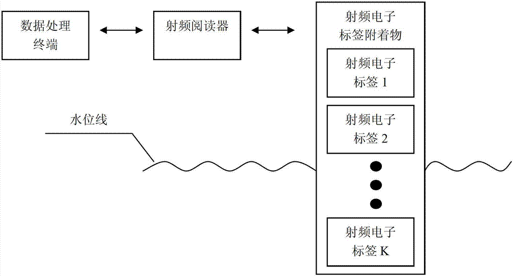
[0038] Embodiment 1: The principle of this embodiment judges the positional relationship between the corresponding RF electronic tag and the water surface by the readable RF electronic tag, and calculates the current water level in combination with the installation position information of each RF electronic tag.

[0039] According to the situation of the water level monitoring site, determine the total number of radio frequency electronic tags to be installed at this water level monitoring point as K, K is a natural number greater than or equal to 2, and make their spacing equal to D in the direction perpendicular to the horizontal plane , D is any value greater than the length of the radio frequency electronic tag itself, the altitude of the highest radio frequency electronic tag is H, after determining the specific installation location information of the radio frequency electronic tag that needs to be installed, the data processing terminal allocates data for each radio frequ...

Embodiment 2

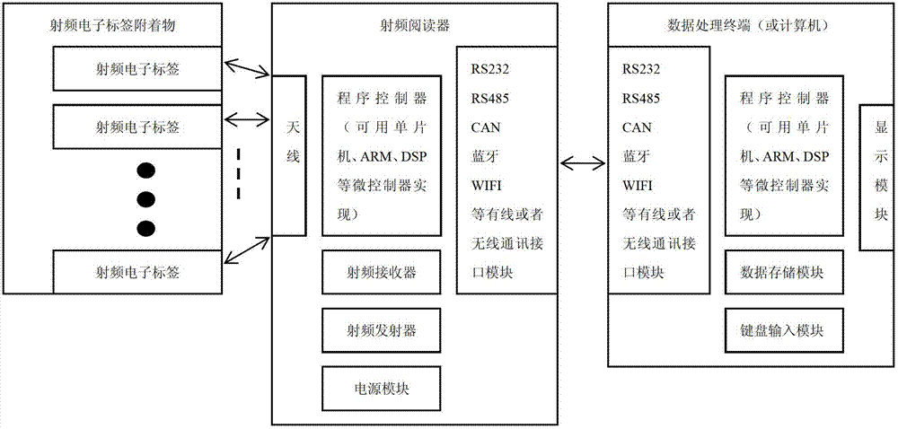
[0042] Embodiment 2: The principle of this embodiment judges the positional relationship between the corresponding RF electronic tag and the water surface by detecting the change in the energy intensity of the RF signal sent by the RF electronic tag received by the RF reader, combined with the installation position of each RF electronic tag The information calculates the current water level.

[0043] When the working state and position relationship between the RF reader and the RF electronic tag are fixed, the main factor for the change of the RF signal energy intensity of the RF electronic tag received by the RF reader is the depth of the RF electronic tag being submerged in water. When the radio frequency electronic tag is far away from the water surface, the radio frequency reader detects that the radio frequency signal energy intensity of the radio frequency electronic tag is basically unchanged. The RF signal energy strength continues to decrease with increasing depth. S...


PUM


Abstract

The invention relates to a water level monitoring method by radio frequency communication method, comprising the following steps: (1) a data processing terminal is connected with a radio frequency reader; if the connection is failed, the equipment is checked and then the radio frequency reader is re-connected; if the connection is successful, the next step is performed; (2) the data processing terminal sends a read operation control instruction to the radio frequency reader; (3) the radio frequency reader reads a radio frequency identification and sends the read data to the data processing terminal; (4) according to the data returned by the radio frequency reader, the data processing terminal looks up relevant installation position information of the radio frequency identification by combining a comparison database which is generated and stored in the data processing terminal during the write-in process of the radio frequency identification data; (5) the data processing terminal compares the read and the unread position information of the radio frequency identification according to the same water level monitoring spot and calculates the range of the present water level. The beneficial effects of the method are simplified equipment installation and convenience in realizing multi-spot water level monitoring.

Description

technical field [0001] The invention relates to the technical field of monitoring, in particular to the technical field of water level monitoring. Background technique [0002] The existing inventions of water level monitoring technology mainly apply the principles of acoustics, electricity and mechanics, which can obtain high measurement accuracy, but the equipment is relatively complicated. Among them, ultrasonic water level monitoring uses the reflection of ultrasonic waves. By measuring the delay time of ultrasonic waves emitted from the transmitting end and received by the receiving end after the reflected ultrasonic waves are returned, the distance from the measuring device to the water surface can be calculated. Electrical water level monitoring can also measure water level using electrodes, making use of the conductivity of water. In addition, mechanical water level monitoring can also realize water level detection by using the buoyancy and pressure of water. The e...

Claims


Application Information

Patent Timeline
Patent Type & Authority Applications(China)
IPC IPC(8): G01F23/284G06K7/00
Inventor 贾楫梁小军张兵
Owner CHENGDU JIUZHOU ELECTRONIC INFORMATION SYSTEM CO LTD
Why Eureka
Try Eureka