
Template setting and template detecting method based on frequency spectrum analysis

A technology of template detection and spectrum analysis, which is applied in the field of spectrum monitoring, can solve the problems of not considering signal influence, difficult application of embedded devices, cumbersome identification process, etc., and achieves friendly human-computer interaction interface, low hardware platform configuration requirements, and real-time identification fast effect

Active Publication Date: 2018-01-12
NO 54 INST OF CHINA ELECTRONICS SCI & TECH GRP
View PDF10 Cites 2 Cited by
  • Summary
  • Abstract
  • Description
  • Claims
  • Application Information

AI Technical Summary

Problems solved by technology

Most of the existing identification signals are modulated signals, which do not consider the influence of the actual complex electromagnetic environment on their signals
Moreover, the signal identification in the current spectrum monitoring is to extract the signal characteristics, extract its signal envelope, match the signal characteristics with the envelope, set the calculation of the correlation coefficient, and identify the signal according to the calculation result. The identification process is cumbersome and the calculation The amount is large, and it is difficult to apply in embedded devices, which reduces the recognition speed

Method used


Image

  • Template setting and template detecting method based on frequency spectrum analysis
  • Template setting and template detecting method based on frequency spectrum analysis
  • Template setting and template detecting method based on frequency spectrum analysis

Examples


Embodiment Construction

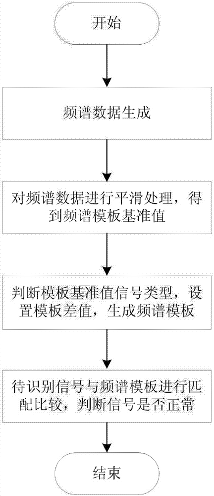
[0033] Implementation steps of the present invention: as figure 1 shown

[0034] Step 1; Spectrum data generation

[0035] The front end of the system realizes AD data acquisition, digital down-converter and fast Fourier transformation through FPGA. The spectrum data generation unit reads the spectrum data of FPGA through DMA mode. Open up two data areas A and B in the storage area, the size of the area is 615 points of data, and each data is 16 bits. The spectrum data is received and stored in a ping-pong structure. Assume that the new data is currently stored in data area A, and the data in data area B is stored and processed at the same time. After the processing of data area B is completed, wait for the completion of data area A to receive. Once the reception is completed, data area A is converted to storage and calculation. Processing flow, at the same time, data area B is converted to receive new data flow, so data areas A and B take turns to receive data and process...


PUM


Abstract

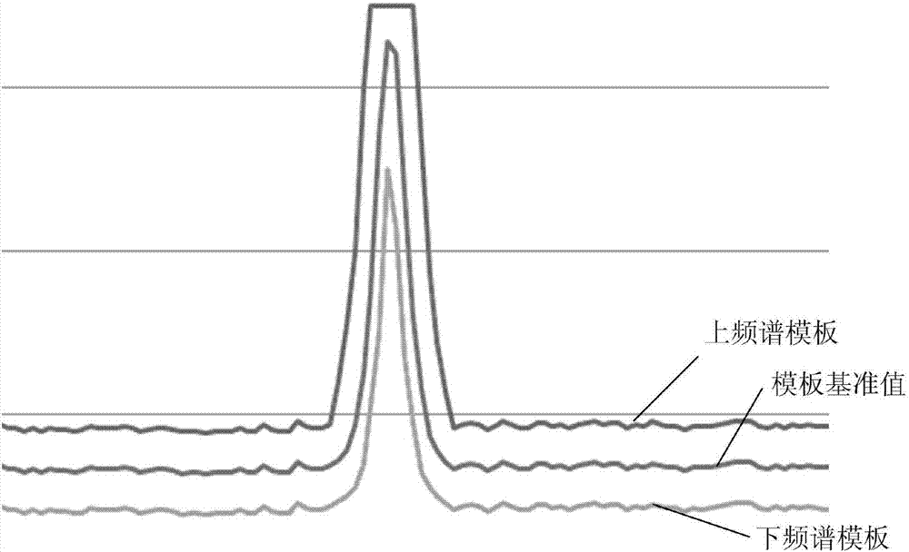
The invention discloses a implementation method for template setting and template detecting, and relates to a method for achieving the template detection function in the field of frequency spectrum monitoring. The method comprises the steps that an FPGA conducts variable frequency conversion and rapid Fourier transform to generate frequency spectrum data, the frequency spectrum data is subjected to smoothing process to generate a frequency spectrum template reference value, the signal type of the frequency spectrum template reference value is judged, and an upper and lower frequency spectrum template is generated by adopting different methods according to different signal types. To-be-identified signals are preprocessed, the to-be-identified signals obtained after preprocessing are compared and matched with the upper and lower frequency spectrum template, the signals exceeding the upper and lower frequency spectrum template range is judged as abnormal signals, warning signals are given, and meanwhile abnormal frequency spectra occurring in the warning process are stored. The method has the advantages of being capable of achieving real-time analysis and real-time display and the like, small in signal feature extraction calculation amount, rapid in real-time processing, high in detection precision and the like. The method is specially suitable for rapid detection on transient abnormal signal in the field of satellite communications, and problems can be sought and located conveniently.

Description

technical field [0001] The invention belongs to the field of frequency spectrum monitoring, and in particular relates to a method for realizing template setting and template detection. Background technique [0002] Spectrum monitoring technology is the main means used to monitor and manage frequency band information. With the development of radio, the use of spectrum resources is also increasing, which makes the use of spectrum resources increasingly tense. A large number of devices work in adjacent frequency bands, which are prone to mutual interference and improve the utilization of spectrum resources. Monitoring abnormal signals has become a major problem. [0003] Identification of abnormal signals is one of the main contents of spectrum monitoring. Common signal recognition is to extract signal features and use pattern recognition for signal recognition. Most of the existing identification signals are modulated signals, which do not consider the influence of the actu...

Claims


Application Information

Patent Timeline
Patent Type & Authority Applications(China)
IPC IPC(8): G01R23/16
Inventor 慈国辉李强张红涛
Owner NO 54 INST OF CHINA ELECTRONICS SCI & TECH GRP
Learn More