Composite permanent-magnet rotor for permanent-magnet motor and manufacturing method thereof

A technology of permanent magnet rotor and permanent magnet motor, which is applied in the direction of magnetic circuit rotating parts, manufacturing stator/rotor body, magnetic circuit shape/style/structure, etc. Magnetic, axial end magnetic flux leakage and other problems, to improve the ability of anti-electromagnetic interference and electromagnetic compatibility, low axial end magnetic flux leakage, and reduce the volume

Inactive Publication Date: 2012-10-31
LINQUAN AEROSPACE MOTOR CO LTD
View PDF5 Cites 9 Cited by
  • Summary
  • Abstract
  • Description
  • Claims
  • Application Information

AI Technical Summary

Problems solved by technology

However, the existing permanent magnet interpolated rotors for permanent magnet motors generally have the problem of magnetic flux leakage at the axial ends, and the pressure plates on both sides of the rotor axial direction must be made of non-magnetic materials, otherwise the rotor axial The flux leakage at the end is more serious
However, this kind of rotor that uses non-magnetic materials to make both side end pressure plates not only has the disadvantages of large volume and low magnetic efficiency, but also has the problems of low strength and short service life.
Therefore the use effect of the rotor that existing permanent magnet motor is used is not ideal enough yet

Method used


Image

  • Composite permanent-magnet rotor for permanent-magnet motor and manufacturing method thereof
  • Composite permanent-magnet rotor for permanent-magnet motor and manufacturing method thereof
  • Composite permanent-magnet rotor for permanent-magnet motor and manufacturing method thereof

Examples


Embodiment 1

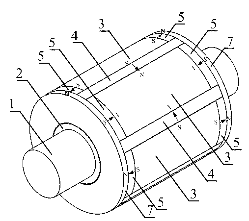
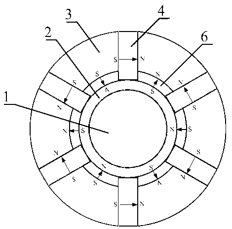
[0023] Embodiment 1 of the present invention: when making the rotor of permanent magnet motor, adopt the composite permanent magnet rotor manufacturing method of a kind of permanent magnet motor of the present invention to make, promptly when rotor iron core is installed on the rotor shaft, first in Put a magnetic sleeve made of magnetic material on the rotor shaft, then make the rotor core into a fan shape, and install and fix the fan-shaped rotor core evenly on the magnetic sleeve, and fix each one on the magnetic shaft Except for the arc-shaped upper end surface of the fan-shaped rotor core on the cover, the other five sides are all surrounded by permanent magnet blocks made of permanent magnetic materials, and make the joint between each permanent magnet block and the fan-shaped rotor core. The polarity of the magnetic poles is the same; when the fan-shaped rotor core is evenly distributed and fixed on the magnetic-conductive shaft sleeve, the fan-shaped rotor core and the ...

Embodiment 2

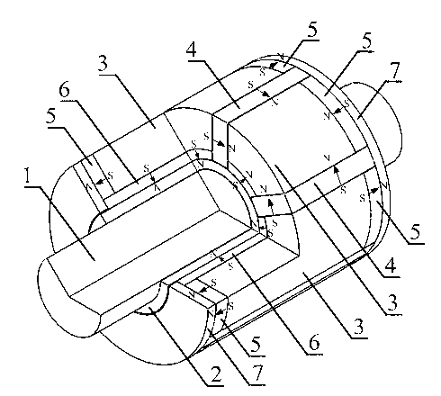
[0025] Embodiment 2: When making the compound permanent magnet rotor of a kind of permanent magnet motor of the present invention, can make according to the method for embodiment 1, when making, also can the axial end portion of the first permanent magnet block 4 top Hold the inner end surface of the end pressure plate 7, leave a gap between the radial inner end surface and the outer surface of the magnetic bushing 2, and the two sides of the second permanent magnet block 5 withstand the first permanent magnet block 4. There is a gap between the three permanent magnet blocks 6 sides (as Figure 6 shown); the rest of the production methods are the same as in Example 1.

Embodiment 3

[0026] Embodiment 3: when making the composite permanent magnet rotor of a kind of permanent magnet motor of the present invention, can make according to the method for embodiment 1, when making, also can connect the axial end of the first permanent magnet 4 with the annular There is a gap between the inner end faces of the end plate 7, a gap is left between the radial inner end face and the outer surface of the magnetically permeable bushing 2, and a gap is left between the sides of two adjacent second permanent magnet blocks 5, adjacent to each other. There is a gap between the two 3rd permanent magnet block 6 sides (as Figure 7 shown); the rest of the production methods are the same as in Example 1.


PUM


Abstract

The invention discloses a composite permanent-magnet rotor for a permanent-magnet motor and a manufacturing method thereof. According to the invention, firstly, a magnetically-conductive shaft sleeve made from a magnetically-conductive material is sleeved on a rotor shaft; then, rotor cores are made into sectors, and the sectorial rotor cores are evenly distributed, mounted and fixed on the magnetically-conductive shaft sleeve; the other five surfaces of each sectorial rotor core mounted and fixed on the magnetically-conductive shaft sleeve except the upper end surface in the shape of a circular arc are all pasted and surrounded by permanent-magnet blocks made from magnetically-conductive materials, and each permanent-magnet block has the same polarity as the magnetic pole of the faying surface of each sectorial rotor core; the sectorial rotor cores and the permanent-magnet blocks are clamped and fixed on the magnetically-conductive shaft sleeve through annular end pressing plates fixed at both ends of the magnetically-conductive shaft sleeve; and the annular end pressing plates are made from magnetically-conductive materials. The composite permanent-magnet rotor has the advantages of compact structure, low flux leakage at axial end parts, high utilization rate of magnetic efficiency of permanent magnets, strong immunity from interference, stable working performance, high rotor strength, long service life and the like.

Description

technical field [0001] The invention relates to a composite permanent magnet rotor of a permanent magnet motor and a manufacturing method thereof, belonging to the technical field of permanent magnet motor manufacturing. Background technique [0002] Permanent magnet motors have the advantages of high efficiency and high power density, and have recently received more and more attention. Among them, the permanent magnet interpolation motor has the advantages of simple processing, and the permanent magnet of the rotor can realize the magnetization effect, which is a kind of permanent magnet motor widely used. However, the existing permanent magnet interpolated rotors for permanent magnet motors generally have the problem of magnetic flux leakage at the axial ends, and the pressure plates on both sides of the rotor axial direction must be made of non-magnetic materials, otherwise the rotor axial The flux leakage at the end is more serious. However, the rotor using non-magneti...

Claims


Application Information

Patent Timeline
Patent Type & Authority Applications(China)
IPC IPC(8): H02K15/03H02K1/27
Inventor 沈建新王灿飞
Owner LINQUAN AEROSPACE MOTOR CO LTD
Why Eureka
Try Eureka