Permanent magnet auxiliary synchronous reluctance motor and mounting method thereof

A technology for assisting synchronous and reluctance motors, applied to synchronous motors with stationary armatures and rotating magnets, electromechanical devices, manufacturing motor generators, etc., to achieve high efficiency

Active Publication Date: 2012-10-31
ZHUHAI GREE REFRIGERATION TECH CENT OF ENERGY SAVING & ENVIRONMENTAL PROTECTION
View PDF6 Cites 25 Cited by
  • Summary
  • Abstract
  • Description
  • Claims
  • Application Information

AI Technical Summary

Problems solved by technology

After actual research and analysis, the above rules proposed in CN

Method used


Image

  • Permanent magnet auxiliary synchronous reluctance motor and mounting method thereof
  • Permanent magnet auxiliary synchronous reluctance motor and mounting method thereof
  • Permanent magnet auxiliary synchronous reluctance motor and mounting method thereof

Examples


Embodiment Construction

[0037] The present invention will be described in detail below with reference to the accompanying drawings and examples. It should be noted that, in the case of no conflict, the embodiments in the present application and the features in the embodiments can be combined with each other.

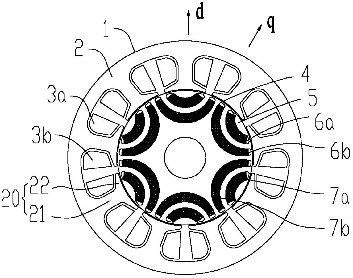
[0038] figure 1 It is a schematic diagram of a permanent magnet assisted synchronous reluctance motor according to the first embodiment of the present invention, which has 6 permanent magnet groups (that is, has 6 poles), each permanent magnet group has 2 layers of permanent magnets, permanent magnet slots and corresponding The permanent magnets are arc-shaped. The following will refer to figure 1 , Figure 6 to Figure 15 The first embodiment will be specifically described.

[0039] Such as figure 1 As shown, the permanent magnet assisted synchronous reluctance motor of the first embodiment includes a stator 1 and a rotor 4 .

[0040] The stator 1 includes a stator core 2 with a plurality...


PUM

PropertyMeasurementUnit
Remanent flux densityaaaaaaaaaa

Abstract

The invention provides a permanent magnet auxiliary synchronous reluctance motor and a mounting method thereof. The permanent magnet auxiliary synchronous reluctance motor comprises a stator and a rotor, wherein the stator comprises a stator iron core and a concentrated winding, and the stator iron core comprises a plurality of convex magnetic poles; the convex magnetic poles comprise magnetic pole teeth and tooth boots, and the widths of the tooth boots are larger than the widths Lc of the magnetic pole teeth; the rotor comprises a rotor iron core and a plurality of permanent magnet groups, and a plurality of permanent magnet slot groups are uniformly distributed on the rotor iron cores; each permanent magnet slot group comprises at least two layers of permanent magnet slots, and each permanent magnet group comprises a permanent magnet arranged in a corresponding permanent magnet slot; the permanent magnets in each permanent magnet slot group have the same polarity, and the polarities of two adjacent permanent magnet groups are opposite; and a relation between a minimum interlayer distance g between two adjacent layers of permanent magnets in each permanent magnet group and the widths T of the tooth boots is disclosed in the specification. According to the permanent magnet auxiliary synchronous reluctance motor, the reluctance torque is maximally utilized, so that the efficiency of the motor reaches a higher level.

Description

technical field [0001] The present invention relates to the field of motors, more specifically, to a permanent magnet assisted synchronous reluctance motor and an installation method thereof. Background technique [0002] The built-in permanent magnet synchronous motor is a motor that places a layer of permanent magnets inside the rotor and uses permanent magnet torque and reluctance torque. It mainly improves the performance of the motor by improving the performance of the permanent magnet. quasi-permanent magnets. However, rare earth is a non-renewable resource, and its price is expensive, so the wider application of this kind of motor is limited. [0003] In order to save rare metal resources and reduce the environmental burden, combining the advantages of synchronous reluctance motors and built-in permanent magnet synchronous motors, it is the general trend to develop permanent magnet assisted synchronous reluctance motors that use a small amount of rare earths or do no...

Claims


Application Information

Patent Timeline
IPC IPC(8): H02K21/14H02K15/00H02K15/03
Inventor 黄辉胡余生陈东锁肖勇曾学英
Owner ZHUHAI GREE REFRIGERATION TECH CENT OF ENERGY SAVING & ENVIRONMENTAL PROTECTION
Why Eureka
Try Eureka