Combined liner for ball mill

A ball mill, combined technology, applied in the direction of grain processing, etc., can solve the problems of small sliding friction, low ball-carrying ability, poor grinding effect of grinding balls, etc., to increase sliding friction, improve ball-carrying ability, and good crushing effect Effect

Active Publication Date: 2014-11-05
HUNAN CHUANGYUAN NEW MATERIALS
View PDF8 Cites 0 Cited by
  • Summary
  • Abstract
  • Description
  • Claims
  • Application Information

AI Technical Summary

Problems solved by technology

[0003] In the patent document with the patent number 02252431.2, a combined liner is recorded, that is, no less than two liners with different surface shapes are installed on the inner wall of the cylinder. The contact area between the grinding ball and the liner is small, the sliding friction is small, and the crushing effect of the grinding ball is poor; the effective volume of the liner is small, and the ball carrying capacity is low; the discharge end adopts a liner with a smooth arc surface, and There is a gentle protrusion in the middle, so that the classification effect of the grinding ball is not obvious
The liner is installed on the cylinder of the ball mill with bolts. After running for a period of time, the surface of the liner is worn and the bolts become loose, resulting in powder leakage from the ball mill and requiring frequent maintenance.

Method used


Image

  • Combined liner for ball mill
  • Combined liner for ball mill
  • Combined liner for ball mill

Examples


Embodiment Construction

[0033] The following will clearly and completely describe the technical solutions in the embodiments of the present invention with reference to the accompanying drawings in the embodiments of the present invention. Obviously, the described embodiments are only part of the embodiments of the present invention, not all of them. Based on the embodiments of the present invention, all other embodiments obtained by persons of ordinary skill in the art without creative efforts fall within the protection scope of the present invention.

[0034] The specific implementation is as follows:

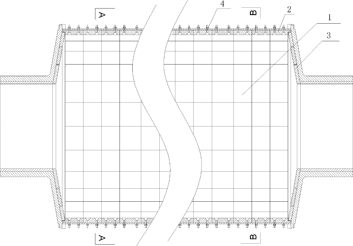
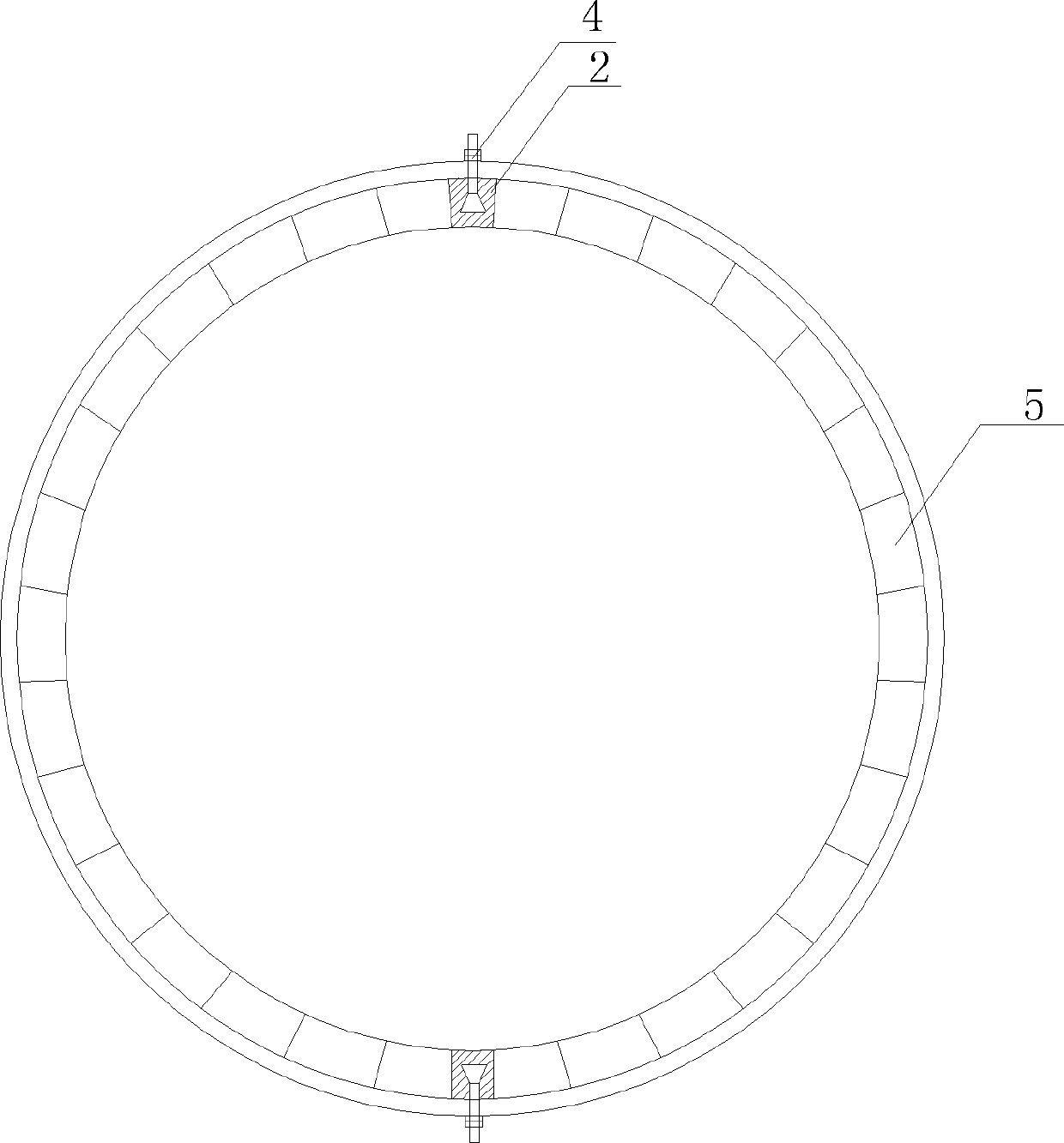
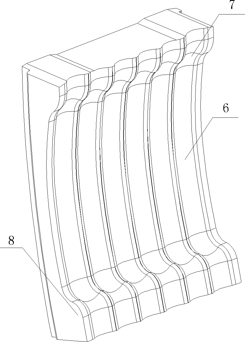
[0035] see Figure 1 to Figure 11 The ball mill combined liner of the present invention includes a cylinder liner 1, a riveting plate 2, and an end liner 3. The back of the cylinder liner 1 forms a corresponding arc surface with the contact surface of the ball mill cylinder, and the cylinder liner 1 includes The material liner 5 and the discharge liner 10 are installed along the axial direction of t...


PUM


Abstract

The invention discloses a combined liner for a ball mill. The combined liner comprises an end liner, a shell liner and a rivet plate. Along the axial direction of a cylindrical shell, several charging liners with wave-shaped working faces are installed at a feed end of the ball mill. A discharge end is provided with several discharge liners with smooth curved working faces. Two ends of the charging liners and the discharge liners are respectively provided with bosses. The working faces of the charging liners are provided with several grooves with circular-arc cross sections. The upper surface of the discharging liner ball bearing boss has a trapezoid structure so as to form a skewed slot which inclines towards a feed end of the ball mill. The combined liner for the ball mill in the invention has high ball bearing ability and good abrasion resistance, and can be used to realize automatic grading of ball milling.

Description

technical field [0001] The invention relates to an anti-wear device, in particular to a ball mill liner. Background technique [0002] Ball mill is a kind of grinding equipment widely used in the fields of electric power, ceramics, cement and mineral processing. Its basic working principle is: the cylinder of the ball mill rotates at a certain speed, and the grinding balls at the bottom of the cylinder of the ball mill are attached to the lining plate of the cylinder under the action of centrifugal force and friction. When the grinding ball is brought to a certain height, it is thrown down due to its own gravity, and the abrasive material at the bottom of the cylinder is impacted and crushed and ground. The liner is the key anti-wear part of the ball mill. The severe impact of the ball on the liner of the ball mill will cause the liner to wear and thin. [0003] In the patent document with the patent number 02252431.2, a combined liner is recorded, that is, no less than tw...

Claims


Application Information

Patent Timeline
Patent Type & Authority Patents(China)
IPC IPC(8): B02C17/22
Inventor 聂勤俭
Owner HUNAN CHUANGYUAN NEW MATERIALS
Why Eureka
Try Eureka