
Submersed nozzle for high-casting-speed continuous casting crystallizer

A continuous casting crystallizer and immersion technology, which is applied in the field of continuous casting of steel, can solve the problems of reducing the impact kinetic energy of molten steel due to friction, poor stability of streams flowing out of side holes, and unfavorable uniformity of billet shell growth, etc., so as to avoid The effects of excessive liquid level fluctuations and slag appearance, improving internal quality, reducing impact and interference to the liquid level

Active Publication Date: 2014-11-05
启东市希士水泥有限公司
View PDF7 Cites 0 Cited by
  • Summary
  • Abstract
  • Description
  • Claims
  • Application Information

AI Technical Summary

Problems solved by technology

The above characteristics lead to the following unfavorable factors during pouring of the submerged nozzle: First, because the bottom surface of the nozzle inner cavity is a smooth plane or inclined surface, after the molten steel hits the bottom surface, it will cause a relatively strong impact rebound, regardless of whether the bottom of the nozzle is convex. , flat bottom or concave bottom, the buffering and kinetic energy consumption of molten steel are relatively small, and the impact of molten steel is strong when pouring at high casting speed, so that the outlet stream has a greater impact on the primary solidified shell, and at the same time, the liquid level fluctuates violently , which is not conducive to the normal growth of the billet shell; secondly, because the wall surface around the side hole of the nozzle is also a smooth plane or slope, the contact area between the side hole wall surface and the molten steel is limited, and the gap between the side wall and the molten steel cannot be well utilized. The friction effect between them reduces the impact kinetic energy of the molten steel, which makes the impact of the molten steel on the billet shell and the liquid surface greater, resulting in quality problems of the billet. At the same time, the stability of the stream flowing out of the side hole is also poor, which is not conducive to the billet shell uniformity of growth

Method used


Image

  • Submersed nozzle for high-casting-speed continuous casting crystallizer
  • Submersed nozzle for high-casting-speed continuous casting crystallizer
  • Submersed nozzle for high-casting-speed continuous casting crystallizer

Examples


Embodiment 1

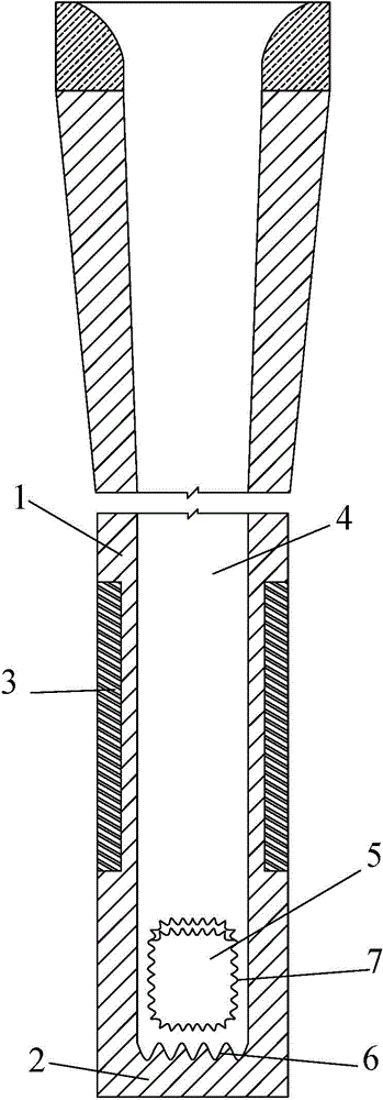
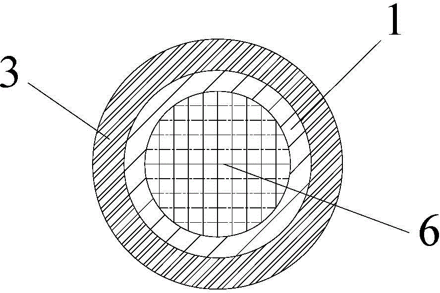
[0030] When pouring a slab with a casting speed of 1.5m / min, such as figure 1 and figure 2In the embodiment of the double-sided holes shown, the cross-sections of the side wall 1 and the inner cavity 4 are both circular during casting. Two side holes 5 of the same size and shape are arranged on the side wall 1 at 20 mm above the upper surface of the bottom cover 2. The holes 5 on both sides are axially symmetrical along the center line of the inner cavity 4 of the nozzle, and the center line of the side holes 5 is in the shape of - The inclination angle of 15°; the upper surface of the back cover 2 is provided with criss-cross wave-shaped grooves 6, the width of the wave-shaped grooves 6 is 5 mm, the depth from the trough to the bottom of the side wall cavity is 6 mm, and the wave crest into the side wall The height of the bottom of the chamber is 2mm, and the distance between adjacent columns and rows is 6mm. The side hole 5 is surrounded by a wavy curved surface 7, and the...

Embodiment 2

[0032] When the pouring speed is 2m / min bloom, you can use such as Figure 6 The shown embodiment with four side holes is poured, and the cross-section of the side wall 1 and the inner cavity 3 is set to be circular. Four side holes 5 of the same size and shape are arranged on the side wall 1 at 20 mm above the upper surface of the bottom cover 2 of the submerged nozzle. The center line is axisymmetric, and the center line of the side hole 5 is at an inclination angle of -15° to the horizontal plane; the upper surface of the back cover 2 is provided with crisscross wavy grooves 6, the width of the wavy grooves 6 is 6mm, and the trough reaches The depth of the bottom of the side wall cavity is 5 mm, the height from the crest to the bottom of the side wall cavity is 1 mm, and the distance between adjacent columns and rows is 6 mm; the side hole 5 is surrounded by a wavy surface 7, and the wavy surface The height difference between the trough and the crest of 7 is 6 mm, and the ...


PUM


Abstract

The invention relates to a submersed nozzle for a high-casting-speed continuous casting crystallizer. The submersed nozzle comprises a side wall and a back cover; slag lines are arranged on the outer surface of the side wall; the back cover is mounted at the lower end of the side wall; the side wall forms an inner cavity with an upper opening in the vertical direction; more than one side hole are formed on the side wall and are positioned close to the upper part of the back cover; the side holes are communicated with the inner cavity of the side wall; the upper surface of the bottom of the inner cavity of the side wall is lower than the lower edge of any one side hole, so that the bottom of the inner cavity of the side wall is concave; and steel liquid flows in the inner cavity of the side wall from the upper opening, impacts the bottom of the inner cavity of the side wall, bounces and flows out from the side holes of the side wall. By adoption of the technical scheme, the bottom of the inner cavity of the side wall can effectively buffer the speed of the steel liquid, so as to dissipate kinetic energy of the steel liquid considerably, reduce the impact strength of the steel liquid at high casting speed, reduce impact of the steel liquid on the blank shell of the wall surface of a crystallizer as well as interference of the steel liquid with the liquid level, and avoid excessive fluctuation and slag entrapment of the liquid level.

Description

technical field [0001] The invention belongs to the technical field of continuous casting of steel, and in particular relates to a slab and a submerged nozzle of a high-speed continuous casting crystallizer for a bloom continuous casting crystallizer whose section size is greater than 200mm×200mm. Background technique [0002] Continuous casting of steel is the process of continuously cooling molten steel with a certain degree of superheat into a solid billet shell with a certain shape through a water-cooled crystallizer. In the continuous casting process of steel, a very important step is to use refractory materials. The submerged nozzle device continuously injects the molten steel in the tundish into the mold. The submerged nozzle is a refractory sleeve installed at the bottom of the tundish and inserted below the liquid level of the mold. Its main function is to prevent secondary oxidation of the molten steel. , nitriding, and splashing, while avoiding slag rolling on the...

Claims


Application Information

Patent Timeline
Patent Type & Authority Patents(China)
IPC IPC(8): B22D11/10B22D41/50
Inventor 徐海伦青雪梅马春武幸伟徐永斌
Owner 启东市希士水泥有限公司
Learn More