
Combined tensioning mechanism for caterpillar band

A combined tensioning and crawler technology, applied to tracked vehicles, motor vehicles, transportation and packaging, etc., can solve the problems of increased impact force and unsatisfactory compression spring adaptability, and achieve reliable performance, simple structure and convenient maintenance.

Inactive Publication Date: 2012-11-07
XUZHOU XUGONG FOUND CONSTR MACHINERY
View PDF10 Cites 5 Cited by
  • Summary
  • Abstract
  • Description
  • Claims
  • Application Information

AI Technical Summary

Problems solved by technology

As the mass (weight) of the working machine continues to increase, the impact force generated by the chassis during the movement will also increase significantly. At this time, the adaptability of the compression spring can no longer meet the requirements of the actual working conditions.

Method used


Image

  • Combined tensioning mechanism for caterpillar band
  • Combined tensioning mechanism for caterpillar band

Examples


Embodiment Construction

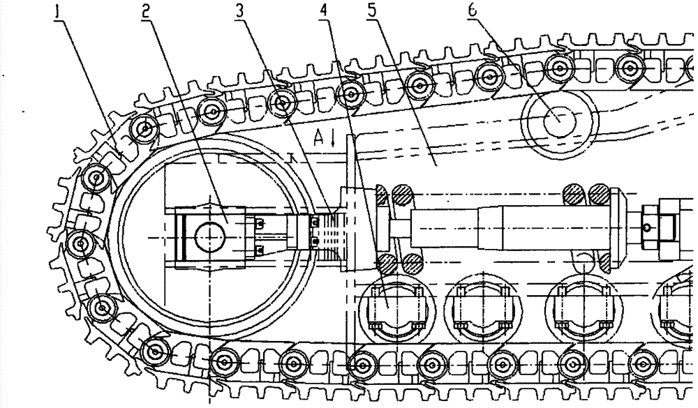
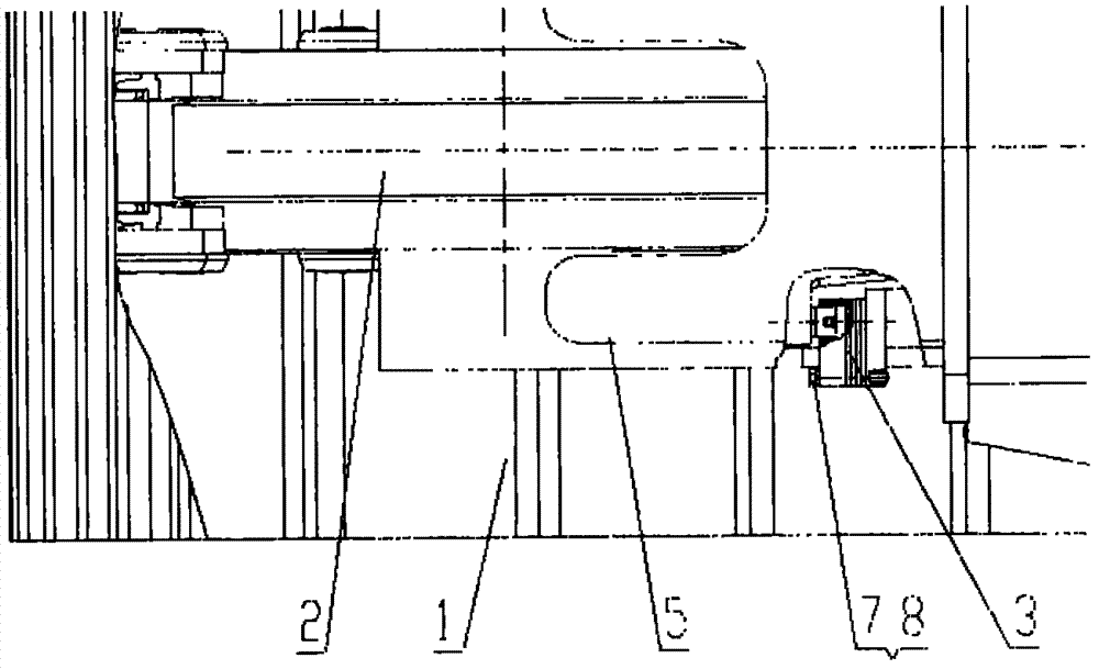
[0012] Install the tensioning device (2) into the inside of the longitudinal beam (5) from one end as required, and ensure that the slide rails on both sides of the guide wheel correctly enter the groove of the longitudinal beam, and at the same time make the exposed end of the cylinder piston rod In the round hole of the beam vertical plate, the oil injection valve points to the outside; then install the track roller (4) and the supporting sprocket (5) on the upper and lower planes of the longitudinal beam (5); flatten the track assembly (1) On the ground, place the longitudinal beam parts that have just been assembled together on the assembly, and then complete the connection of the head and tail pins of the track. Then add grease to the oil cylinder of the tensioning device. With the continuous increase of the total length of the part, a certain gap will be formed between the lugs on both sides of the support and the bracket welded at the rectangular hole of the longitudinal...


PUM


Abstract

The invention relates to a combined tensioning mechanism for a caterpillar band, which meets the special requirement on the practical tension variation by a caterpillar band assembly when a large engineering machinery caterpillar band chassis is on a smooth road surface and under a field pathless condition. The mechanism consists of a caterpillar band assembly, a tensioning device, a longitudinal beam and the like, wherein the sliding rail of the tensioning device and support lugs at the two sides of the support are arranged in a groove of a fender at the end part of the longitudinal beam; vertical plates at the two sides of the fender are respectively provided with a rectangular hole and a bracket used for installing and fixing an adjustable pad and are connected by bolts; and the exposed end of an oil cylinder piston rod at the other end is arranged in the round hole of the vertical plate of the longitudinal beam. When the caterpillar band requires smaller tensioning force, grease is filled into the oil cylinder of the tensioning device to regulate the tensioning force. In the chassis driving process, once the impact load of the chassis exceeds the limit of the chassis, an elastic gap is eliminated, the balance of extra-large tensioning force is directly borne by the support lugs arranged at the two sides of the support and the adjustable pad between the brackets of the groove of the longitudinal beam fender so as to maintain the normal work of the chassis.

Description

technical field [0001] The invention relates to a chassis of a rotary drilling rig with a crawler structure. The primary tension force of the crawler is adjusted by changing the stroke of the oil cylinder in the tensioner. When the impact load of the chassis movement is too large, the rigidity of the tensioner is changed through a preset mechanism. , to meet the balance of the actual load, especially suitable for the track chassis of large and medium-sized construction machinery. Background technique [0002] At present, in order to ensure the smoothness of the movement during the walking of the rotary drilling rig and prevent the excessive slack of the crawler belt from causing the driving wheel to skip teeth, most of the longitudinal beam structures of the chassis of construction machinery containing crawler parts are equipped with a special structure with adjustable crawler tension. . During the running of the chassis, once the crawler belt is excessively loose or the dr...

Claims


Application Information

Patent Timeline
Patent Type & Authority Applications(China)
IPC IPC(8): B62D55/08B62D55/30
Inventor 吴兆成张忠海韩立华陈波群朱海港
Owner XUZHOU XUGONG FOUND CONSTR MACHINERY
Learn More