
Pneumatic motor

A technology of air motor and exhaust flow, applied in machine/engine, rotary piston engine, rotary or oscillating piston engine, etc., can solve the limitation of the number of blades of air motor, the torque efficiency is not significantly improved, and the torque cannot be stabilized Output and other issues to achieve the effect of improving torque efficiency and output torque efficiency

Inactive Publication Date: 2012-11-07
HYPHONE MASCH IND CO LTD
View PDF9 Cites 11 Cited by
  • Summary
  • Abstract
  • Description
  • Claims
  • Application Information

AI Technical Summary

Problems solved by technology

[0004] When the user further increases the number of blades, the mandrel in the rotor may have too many blades and too many grooves, so that the mandrel has a problem of low structural strength, and the blades of the air motor The number of settings is limited, and it is impossible to obtain a more stable torque output by adding blades
[0005] In addition, adding more vanes to the mandrel can theoretically increase the contact with the high-pressure gas and obtain a greater torque output effect, but in practice, it has been found that the increase in the number of vanes will cause the vanes to contact with the inner wall of the cylinder during the rotation of the mandrel. Circular friction is more obvious, resulting in not only no significant improvement in torque performance, but the rotor rpm is reduced to 10% of the working range allowed by the industry, which in turn affects the working performance of pneumatic tools
[0006] Generally speaking, the current design of the cylinder rotor structure of pneumatic tools is still waiting for the industry to propose a more perfect design plan, in order to design a design that can greatly increase the output torque of the air motor cylinder without reducing the rotation speed of the cylinder rotor. New air motor with 10% working range despite the reduction

Method used


Image

  • Pneumatic motor
  • Pneumatic motor
  • Pneumatic motor

Examples


Embodiment Construction

[0037] The following examples are only used to illustrate possible implementation modes of the present invention, and are not intended to limit the protection scope of the present invention.

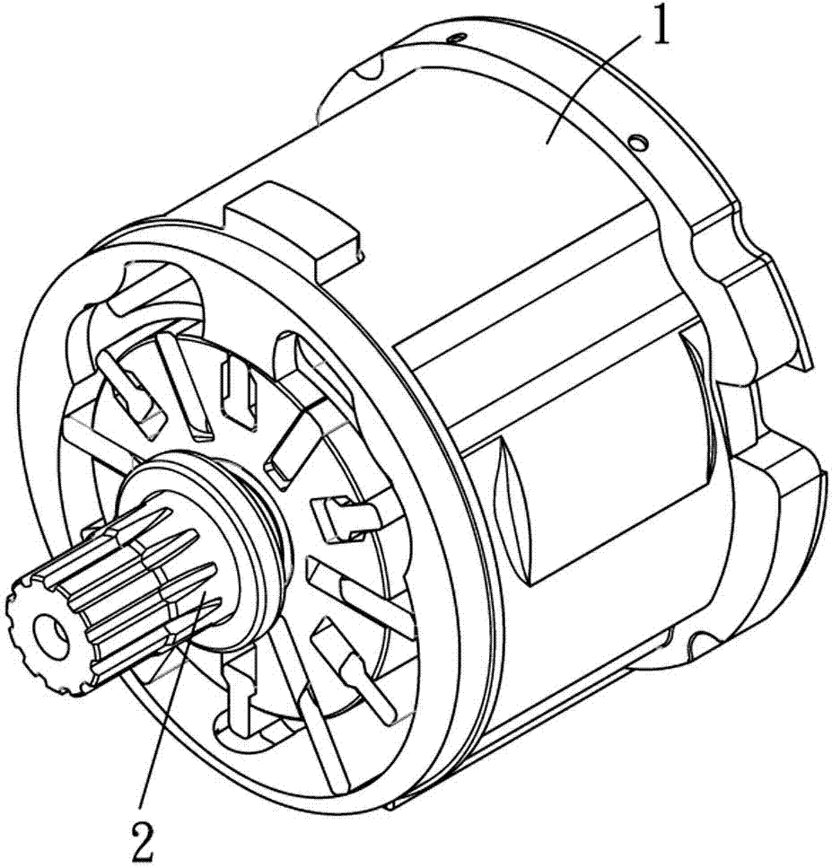
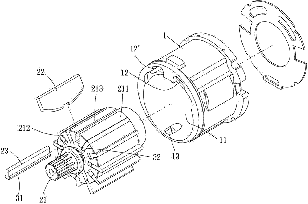
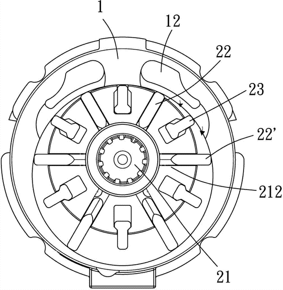
[0038] Please refer to figure 1 and figure 2 , The present invention provides an air motor, which is installed in various air tools and driven by high-pressure gas to further drive the air tools to work. The air motor provided by the present invention includes a cylinder 1, a rotor 2 and a limiting device.

[0039] The cylinder 1 is surrounded by an accommodating groove 11 , an intake flow passage 12 and an exhaust flow passage 13 , and the intake flow passage 12 and the exhaust flow passage 13 communicate with the accommodating groove 11 respectively. The cylinder 1 has an inner wall, which is located on the peripheral surface of the housing tank 11. Through this structural design, high-pressure gas can enter the housing tank from the outside through the intake channel 12, and then b...


PUM


Abstract

The invention provides a pneumatic motor, which comprises a cylinder and a rotor. The cylinder is enclosed by a storage tank, air inlet channels and an air outlet channel, wherein the air inlet channels and the air outlet channel respectively communicate with the storage tank. The cylinder is provided with an inner wall which is positioned on the circumferential surface of the storage tank. The rotor comprises a mandrel, a plurality of main vanes and a plurality of auxiliary short vanes, wherein the mandrel is off center and is rotatablely arranged in the storage tank. A plurality of main chutes and auxiliary chutes which are recessed in the radial direction of the mandrel are arranged in a circle on the outer peripheral face of the mandrel. Each main vane which can radially slide is slidably arranged on the main chutes, and each auxiliary vane which can radially slide is slidably arranged on the auxiliary chutes. When the mandrel rotates, each main vane rotates with the mandrel and abuts against the inner wall. Parts of the auxiliary vanes with rotation angles contact with the inner wall of the cylinder when the mandrel rotates. According to the invention, on the prerequisite that the rotating speed of the rotor is maintained within permissible range of working speed, output torque of the cylinder can be greatly raised.

Description

technical field [0001] The present invention relates to an air motor, in particular to a rotor of the air motor. Background technique [0002] The working principle of the air motor is driven by compressed air, providing torque output, and further driving other tools to rotate. Among them, in order to increase the output power of the existing air motor, various devices or adjustment mechanisms are arranged on the air motor. For example, China Taiwan Patent No. I259865 discloses an air motor, which is provided with two sets of air intake holes and exhaust holes, and is provided with a control valve group to control the opening or closing of each air intake hole and exhaust hole, thereby extending the compression period. The power stroke of the gas in the air motor obtains a larger torque output. [0003] However, the stability of the power output of the existing air motor still needs to be further improved. Please refer to the air motor described in Taiwan Patent No. M3885...

Claims


Application Information

Patent Timeline
Patent Type & Authority Applications(China)
IPC IPC(8): F01C1/344
Inventor 丁志明
Owner HYPHONE MASCH IND CO LTD
Learn More