

BS speed reducer
A technology of reducer and machine body, which is applied in the direction of mechanical equipment, transmission parts, friction transmission devices, etc., can solve the problems of affecting the output accuracy, easy wear of parts, and unstable transmission, etc., and achieves compact structure, large transmission power, and transmission smooth and reliable results
- Summary
- Abstract
- Description
- Claims
- Application Information
AI Technical Summary
Problems solved by technology
Method used
Image

Examples
Embodiment Construction
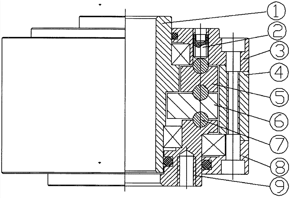
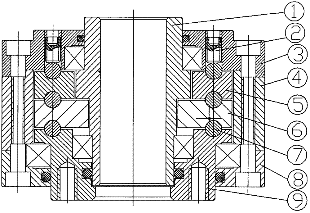
[0009] The preferred embodiment of the present invention is like this, with reference to figure 1 , figure 2 As shown, this reducer is a reducer that can achieve the ideal reduction transmission effect without gear transmission. The balls are used as the transmission medium between the transmission parts, and the gap adjustment screw on the input shaft cover is used to adjust, so that the balls and The S-shaped cycloidal grooves on the two transmission parts are in close contact, and can roll smoothly along the regular S-shaped cycloidal grooves on the two transmission parts, so as to achieve stable and reliable transmission, low noise, zero clearance, and a transmission efficiency of 88 -93%; specifically: a BS reducer, including an input shaft, an input shaft cover, a gap adjustment screw, a body, a fixed plate, a drive plate, balls, an output shaft, and an output shaft cover, wherein the body 4 Install the input shaft 1, the fixed plate 5, the drive plate 6 and the output...
PUM
 Abstract
Description
Claims
Application Information