Light emitting diode (LED) light source coupling device for optical fiber illumination

A coupling device and optical fiber lighting technology, which is applied to lighting devices, components of lighting devices, lighting and heating equipment, etc., to achieve good application prospects, simple design and processing, and small size

Inactive Publication Date: 2012-11-07
GUANGDONG UNIV OF TECH
View PDF3 Cites 4 Cited by
  • Summary
  • Abstract
  • Description
  • Claims
  • Application Information

AI Technical Summary

Problems solved by technology

The light efficiency of the reflector is as high as 90%, and some special coatings can even reach more than 95%, while the commonly used PMMA lens has a light efficiency of up to 94%, and the light efficiency will drop to about 80% or even lower after multi-lens stacking

Method used


Image

  • Light emitting diode (LED) light source coupling device for optical fiber illumination
  • Light emitting diode (LED) light source coupling device for optical fiber illumination
  • Light emitting diode (LED) light source coupling device for optical fiber illumination

Examples


Embodiment Construction

[0022] Below in conjunction with accompanying drawing, the implementation of the present invention is described in further detail

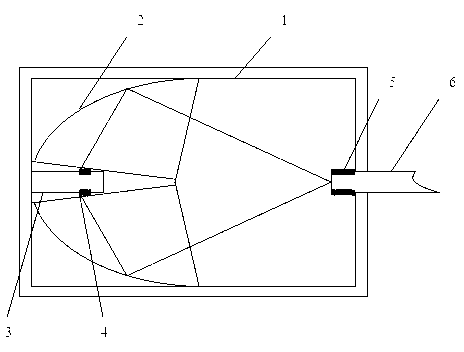
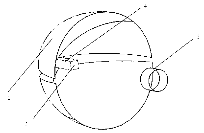
[0023] Such as figure 1 with figure 2 As shown, the LED light source coupling device for optical fiber lighting of the present invention includes a light cylinder body 1, and an elliptical reflector 2 placed in the light cylinder body 1, a heat sink 3, an LED light source 4, and an optical fiber fixed port 5. Fiber optic 6 on fiber optic fixed port 5. The LED light source 4 is placed at the left focal point of the elliptical reflector 2 , and the incident end face of the optical fiber 6 is placed at the right focal point of the elliptical reflector 2 . The LED light source 4 is installed on both sides of the heat sink 3 .

[0024] Optical fiber 6 is a large-aperture polymer optical fiber with a diameter of 10 mm and a numerical aperture NA=0.5, and the numerical aperture angle of the optical fiber is .

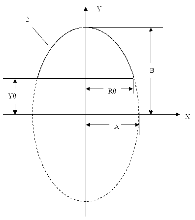
[0025] In this embodiment, the refle...


PUM


Abstract

The invention discloses a light emitting diode (LED) light source coupling device for optical fiber illumination. The device comprises a light barrel, an elliptical reflector, a radiating fin, an LED light source, an optical fiber fixing port and an optical fiber, wherein the elliptical reflector, the radiating fin, the LED light source and the optical fiber fixing port are placed in the light barrel; and the optical fiber is arranged at the optical fiber fixing port. The LED light source is placed on the left focus of the elliptical reflector, the incidental end face of the optical fiber is placed on the right focus of the elliptical reflector, and rays emitted by the light source are reflected to the right focus, coupled to the optical fiber and transmitted. Two LED lamp beads of the LED light source are arranged on the side of the columnar radiating fin. The coupling device for the optical fiber illumination is high in coupled light efficiency, easy to design and machine and small in size.

Description

technical field [0001] The invention relates to the application field of optical fiber lighting, in particular to an LED light source coupling device for optical fiber lighting. Background technique [0002] Fiber optic lighting system has become the new darling of lighting technology because of its high design freedom, safe and reliable use, long life and simple maintenance. The successful development of low-cost high-performance polymer optical fibers in the 1980s made optical fiber lighting more and more popular, and because of its photoelectric separation characteristics, it is widely used in special lighting places such as interior decoration, water features, buildings, and flammable and explosive lighting. LED is known as the green lighting source in the 21st century because of its long life, low energy consumption, short response time, small size and impact resistance. It is the development trend of today's fiber optic lighting to organically combine LED and fiber op...

Claims


Application Information

Patent Timeline
Patent Type & Authority Applications(China)
IPC IPC(8): F21V13/02F21V7/08F21Y101/02
Inventor 苏成悦付倩周镇
Owner GUANGDONG UNIV OF TECH
Why Eureka
Try Eureka