Two-phase flow dynamic heat pipe system

A fluid power and heat pipe technology, applied in the field of heat exchange, can solve the problems of insufficient circulating power and incomplete gas-liquid separation, so as to reduce the limitations of use conditions, solve the problems of high and low position difference and conveying distance, and improve the heat exchange efficiency.

Active Publication Date: 2012-11-07
BEIJING FULLLINK OREITH TECH CO LTD
View PDF9 Cites 10 Cited by
  • Summary
  • Abstract
  • Description
  • Claims
  • Application Information

AI Technical Summary

Problems solved by technology

[0006] A new type of heat pipe heat exchange device technology provided by the present invention—a two-phase flow power heat pipe system i

Method used


Image

  • Two-phase flow dynamic heat pipe system
  • Two-phase flow dynamic heat pipe system
  • Two-phase flow dynamic heat pipe system

Examples


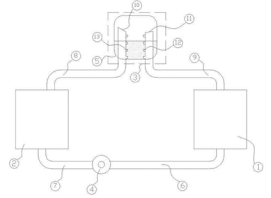
specific Embodiment approach 2

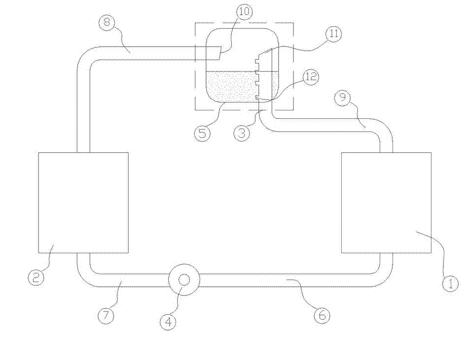
[0029] In a specific environment, in order to exchange the functions of the condenser (1) and the evaporator (2) in the system, that is, the condenser (1) acts as an evaporator, and the evaporator (2) acts as a condenser. Improvements are made on the basis of the first embodiment.

[0030] The circulation pump (3) is replaced by a one-way circulation pump with a two-way power motor system (such as a Roots motor) that can directly change the direction. The part of the air pipe (9) in the liquid storage and diversion device (3) has the same design, and part of it is located at the lower part of the liquid surface in the liquid storage tank (5), and the backflow hole two (13) and the backflow hole with a certain interval are respectively distributed on the top One (12), and the output end of the evaporator (10) and the input end of the condenser (11) are both above the liquid surface in the liquid storage tank (5). The simple structural diagram of this embodiment is shown in ...


PUM


Abstract

The invention discloses a two-phase flow dynamic heat pipe system which mainly comprises a condenser, a liquid storing and flow splitting device, a circulating pump, an evaporator and a circuit control element. The liquid storing and flow splitting device consists of a liquid storing tank, input and output ends of a gas-guide tube and backflow holes, so that gas flow and liquid flow are collected, thoroughly separated and split, and the integral system has a stable circulation of the gas flow and the liquid flow; the backflow holes include liquid return holes and gas return holes, the gas return holes are positioned above the liquid level inside the liquid storage tank, and the liquid return holes are positioned below the liquid level inside the liquid storage tank; energy is transmitted via the condenser and the evaporator which are used as two heat exchangers; the circulating pump is connected between a liquid inlet end of the evaporator and a liquid outlet end of the condenser; and the circuit control element controls the running state of the system. By the aid of the liquid storing and flow splitting device and the circulating pump, problems that gas and liquid in heat exchange equipment with heat pipes are not separated from each other thoroughly and circulating power is insufficient are solved, work efficiency and practicality of heat pipes are improved, and the integral system is simple in device structure and is environment-friendly.

Description

technical field [0001] The invention relates to the technical field of heat exchange, in particular to a novel heat pipe heat exchange system, in particular to a split-type two-phase flow heat pipe system with a circulation pump. Background technique [0002] As a high-efficiency heat transfer element, heat pipes are increasingly used in engineering. Heat pipes are not only widely used in waste heat recovery, cooling of electronic components, etc., but also in the field of traditional heat and mass transfer equipment, heat pipes have a tendency to replace circulating water, circulating oil and steam for heat transfer. When the ambient temperature is low, the heat pipe can also replace the current air-conditioning system as a cooling and temperature control element for electronic equipment, power equipment, computer rooms, and communication rooms. [0003] Heat pipes have a variety of structural forms, and there are also a variety of classification methods. Classified accor...

Claims


Application Information

Patent Timeline
IPC IPC(8): F28D15/02
CPCF28D15/0266
Inventor 祝长宇丁式平
Owner BEIJING FULLLINK OREITH TECH CO LTD
Why Eureka
Try Eureka