Double limited self-locking ball screen

A self-locking, ball net collection technology, applied in the field of heat exchanger cleaning, can solve problems such as difficult to detect, unreasonable structure, excessive transmission, etc., and achieve the effect of stable work, simple structure and high reliability

Inactive Publication Date: 2012-11-07
于转云
View PDF6 Cites 5 Cited by
  • Summary
  • Abstract
  • Description
  • Claims
  • Application Information

AI Technical Summary

Problems solved by technology

The above-mentioned products mainly have the following problems during the use of the common ball collecting nets in the prior art: 1) The existing ball collecting nets have problems such as unreasonable structure, unstable transmission mechanism, and easy wear and tear. There are phenomena such as ball running, ball accumulation, ball jamming, and ball pinching; 2) The ball collecting net itself does not have a self-locking function, and it is only controlled and limited by electric actuators in various working conditions, so that actuators often appear in use. If the operating angle is too high, the net plate cannot be closed tightly, and it is not easy to be detected (it cannot be found from the outside, it only shows that the ball collection rate is low); Basically parallel, unable to achieve backwashing, it can only wash away the sundries accumulated on the surface of the net, and cannot clean up the sundries in the grille; 4) The control part of the original net needs too much power, Not suitable for manual operation when the electric actuator fails
The device reduces components, simplifies the structure, and reduces the cost. When the screen plate is working at the limit position of the ball collection and cleaning conditions, the connecting rod and the crank are in line, and the self-locking effect is achieved through the control of the external electric actuator. purpose, but there are still disadvantages of excessive transmission and difficulty in achieving the backwash state

Method used


Image

  • Double limited self-locking ball screen
  • Double limited self-locking ball screen
  • Double limited self-locking ball screen

Examples


Embodiment 1

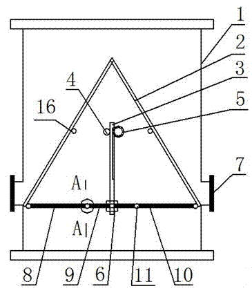
[0013] Embodiment 1: The connecting rod II9 in the three-link driving device is connected to the rack 3 through the installation hole, the bottom of the rack 3 passes through the connecting rod II9 and is threaded to the lock nut 6, and the toothed side of the rack 3 meshes The gear 5 and the toothless side of the rack 3 are in contact with the positioning roller 4. In this way, when the rack 3 moves up and down under the drive of the gear 5, the positioning roller 4 can be used to determine the longitudinal position of the rack 3 and ensure Under various working conditions, the gear 5 and the rack 3 are tightly meshed. During design, the setting of the number of teeth of the gear 5 and the number of teeth of the rack 3 is completed in such a way: when the ball collecting net is in the ball collecting working condition, the gear 5 reaches the top of the rack 3; Under normal circumstances, the gear 5 arrives at the bottom of the rack 3; Through this kind of design, it can prev...

Embodiment 2

[0016] Embodiment 2: The difference between this embodiment and Embodiment 1 is that the structure of the rack 3 is changed, so that both sides of the rack 3 have protruding teeth, so that the teeth on both sides can mesh with the gear 5 , the transmission life of the double-sided structure rack 3 is greatly extended, and the transmission carrying capacity is also increased at the same time, and the transmission is more stable and smooth.

Embodiment 3

[0017] Embodiment 3: The difference between this embodiment and Embodiment 1 is that a screw transmission mechanism is used to complete the driving of the three linkages, and realize the conversion of the three working conditions of the ball net. The connecting rod II 9 is connected with a rotating screw 14 through the mounting hole, the bottom of the rotating screw 14 is threaded with the locking nut 6, and the rotating screw 14 is also threaded with a fixed nut. Also be provided with protective cover 15 on this screw transmission. In this way, when the rotating screw rod 14 is driven by external force to rotate, through the screw transmission, the connecting rod II9 is ​​driven upward, and moves to the backwashing working condition or the non-commissioning state.

[0018] In the above-mentioned embodiment, a limit block 12 can be provided at an appropriate position on the side of the movable limit card slot 11, and the installation of the limit block again limits the accurac...


PUM


Abstract

The invention discloses a double limited self-locking ball screen. The ball screen comprises a cylinder, an otter board arranged in the cylinder, and a ball outlet arranged on a side wall of the cylinder. A three-link-rod driver is connected at a bottom end of the otter board, and comprises a first link rod, a second link rod and a third link rod, which are connected with one another through a movable limiting clip slot. The second link rod is connected with a rack through a mounting hole. The rack has bottom threads connected with a locking nut, one teeth side engaged with a gear, and the other teeth-free side arranged with a positioning roller. The inventive ball screen adopts the three-link-rod driver to realize three states of the ball screen, can achieve the basic function, but also thoroughly clean the otter board under the back flushing condition, and has advantages of simple structure, low abrasion of a movement mechanism, high ball collecting ration, good operation stability, and high reliability.

Description

technical field [0001] The invention relates to the technical field of heat exchanger cleaning, in particular to a double-limit self-locking ball collecting net used for cleaning cooling water pipelines of thermal power generation, nuclear power and various tubular heat exchangers. Background technique [0002] The rubber ball cleaning system is used to complete the cleaning of the tubular heat exchanger. It uses rubber balls to repeatedly clean the condensing pipes to ensure the cleaning coefficient of the heat exchange tubes in the steam turbine and other condensers, thereby improving the power generation efficiency of the generator set and effectively preventing heat transfer. The fouling and corrosion of the tubes can be prevented, and the service life of the heat exchange tubes can be extended to the greatest extent. The ball collecting net is the key equipment in the rubber ball cleaning system. It is installed on the outlet pipe section of the condenser circulating wa...

Claims


Application Information

Patent Timeline
Patent Type & Authority Applications(China)
IPC IPC(8): F28G15/00F28G1/12
Inventor 于转云
Owner 于转云
Why Eureka
Try Eureka