
Holographic sensor, combination device, subdermal implant and correlation methods

A sensor and implant technology, applied in the field of holographic sensors

Inactive Publication Date: 2012-11-07
CAMBRIDGE ENTERPRISE LTD +1
View PDF7 Cites 0 Cited by
  • Summary
  • Abstract
  • Description
  • Claims
  • Application Information

AI Technical Summary

Problems solved by technology

The device may not always be effective if the sensor is used in an environment where light scatter is substantial such as subcutaneously

Method used


Image

  • Holographic sensor, combination device, subdermal implant and correlation methods
  • Holographic sensor, combination device, subdermal implant and correlation methods
  • Holographic sensor, combination device, subdermal implant and correlation methods

Examples


Embodiment Construction

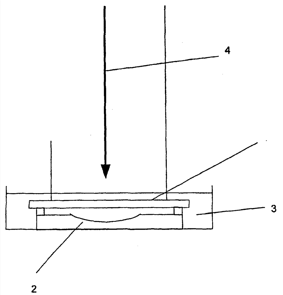
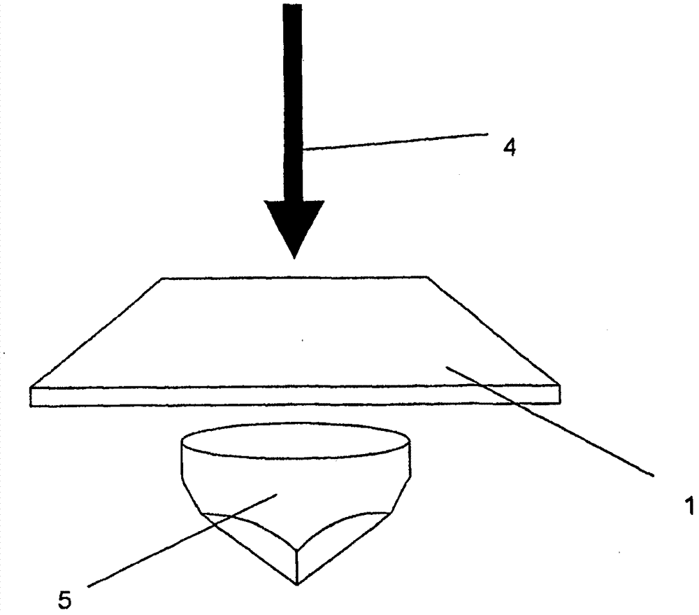
[0025] Holograms can be formed into non-planar mirrors in a number of ways. It will be appreciated that the different techniques described herein can be used alone or in combination to achieve results.

[0026] A preferred embodiment of the invention involves recording holograms using non-planar mirrors. The type of mirror chosen depends on the desired effect on the incident light of the resulting hologram. Many different types of non-planar mirrors are known, such as concave and convex mirrors (eg semi-cylindrical mirrors), reflective beads, and the like. Alternatively the mirror may be a prism such as a corner cube prism, a right angled prism, a Porro prism, an Amici prism, a Dove prism, a pentaprism, a rhomboid prism or a Lernan-Springer prism

[0027] In a preferred embodiment the mirror is a concave mirror. This allows the fabrication of sensors that have a focusing effect on incoming light. The sensor has a wide range of potential uses, for example as a small subcuta...


PUM


Abstract

The invention relates to a holographic sensor, a combination device, a subdermal implant and correlation methods. The sensor (8) comprises a medium and a hologram disposed throughout the volume of the medium, wherein an optical characteristic of the hologram changes as a result of a variation of a physical property of the medium, and wherein the hologram is formed as a non-planar mirror.

Description

[0001] This application is a divisional application of the invention patent application with the name "holographic sensor" and application number 200480024257.5 submitted on July 21, 2004. technical field [0002] The present invention relates to holographic sensors. Background technique [0003] WO-A-95 / 26499 discloses a holographic sensor. The sensor includes a holographic support medium and a hologram located throughout the medium. The supporting medium interacts with the analyte, causing changes in the physical properties of the medium. The change causes a change in the optical characteristics of the holographic element, such as deflectability, reflectivity, refractive index or absorbance. When replaying the hologram (eg, using incident broad-wave, non-ionizing electromagnetic radiation), any changes, if any, are observed using optical detectors, such as color changes. Optical detectors can be spectrometers or just the naked eye. [0004] Another method of manufactur...

Claims


Application Information

Patent Timeline
Patent Type & Authority Applications(China)
IPC IPC(8): G01N21/17G02B5/32G01N21/47
CPCG03H2001/0417G03H2001/0439G03H2001/043G03H2270/21G03H2222/16G02B5/32G03H2001/2615G03H2001/0033G03H1/0005G01N21/4788G03H2001/0044G03H2001/0432G02B5/09G11B7/0065
Inventor 杰弗里·布莱思克里斯托弗·R·洛科林·A·B·戴维森萨蒂亚穆尔蒂·卡比兰凯瑟琳·A·多布森
Owner CAMBRIDGE ENTERPRISE LTD
Learn More