Quick-response current-limiting protection circuit

A fast-response, current-limiting protection technology, applied in emergency protection circuit devices, emergency protection circuit devices for limiting overcurrent/overvoltage, circuit devices, etc. Difficult to implement and other problems, to achieve the effect of simplified calculation and design, low response time, and easy circuit implementation

Active Publication Date: 2012-11-07
SG MICRO
View PDF7 Cites 14 Cited by
  • Summary
  • Abstract
  • Description
  • Claims
  • Application Information

AI Technical Summary

Problems solved by technology

This undoubtedly increases the difficulty of determining the parameters of the circuit and its components
In addition, in the common CMOS process, npn transistor (i.e. triode Q1) is difficult to realize
Even if manufacturers can manufacture npn, the cost is higher than that of chips produced by common CMOS process

Method used


Image

  • Quick-response current-limiting protection circuit
  • Quick-response current-limiting protection circuit
  • Quick-response current-limiting protection circuit

Examples


Embodiment Construction

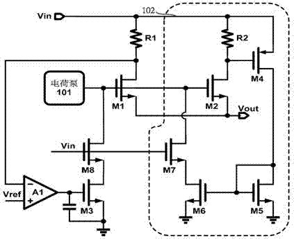
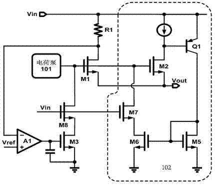
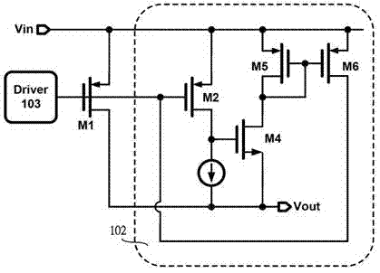
[0026] Below with the accompanying drawings ( Figure 2-Figure 9 ) to illustrate the present invention.

[0027] Such as Figure 2-Figure 9 As shown, a fast-response current-limiting protection circuit 102 includes the first MOS tube, that is, the power switch tube M1 (such as Figure 2-Figure 9 M1) The second MOS transistor connected to the gate is the current sensing MOS transistor M2 (such as Figure 2-Figure 9 M2), the source of the current sensing MOS transistor M2 is directly interconnected with the source of the power switch M1, and the drain of the current sensing MOS transistor M2 is connected to a voltage divider circuit (such as Figure 2-Figure 9 in R2 or at the current source mark), the voltage divider circuit is connected to a fast-response current-limiting switch circuit. The voltage dividing circuit includes a second resistor, that is, a voltage dividing resistor R2. The voltage dividing circuit includes a current mirror. The fast-response current-limiting...


PUM


Abstract

A quick-response current-limiting protection circuit can quickly response the change of the output current of the power switch tube and timely limit the output current to a safe range, and wait for a precise current-limiting circuit having slow start and high precision and consisting of a monitoring resistor, a comparator and an MOS (Metal Oxide Semiconductor) tube to further precisely adjust the output current, thus realizing the combination of the quick current limitation and precise current limitation. The quick-response current-limiting protection circuit is characterized by comprising a second MOS tube, namely a current induction MOS tube, which is connected with the first MOS tube, namely the grid electrode of the power switch tube, wherein the source electrode of the current induction MOS tube is directly connected with the source electrode of the power switch tube; and the drainage electrode of the current induction MOS tube is connected with a bleeder circuit which is connected with a quick-response current-limiting switch circuit.

Description

technical field [0001] The invention relates to microelectronic integrated circuit technology, in particular to a fast-response current-limiting protection circuit. The fast-response current-limiting protection circuit can quickly respond to changes in the output current of the power switch tube, limit the output current within a safe range in time, and wait for the slow-starting but high-precision accurate current-limiting circuit consisting of a monitoring resistor, a comparator and a MOS tube. The circuit further precisely adjusts the output current to achieve a combination of fast and precise current limiting. Background technique [0002] When encountering events such as hot swapping, equivalent load resistance suddenly decreasing, or output short-to-ground, the power switch needs a current-limiting circuit that can respond quickly to suppress the sudden surge in output current and protect the internal large-scale The power MOS tube and the upstream power bus are safe....

Claims


Application Information

Patent Timeline
Patent Type & Authority Applications(China)
IPC IPC(8): H02H9/02
Inventor 郑辰光肖飞其他发明人请求不公开姓名
Owner SG MICRO
Why Eureka
Try Eureka