Differential amplifying circuit capable of automatically adjusting amplification factor

A differential amplifying circuit and magnification technology, applied in differential amplifiers, DC-coupled DC amplifiers, etc., can solve problems such as incomprehension, complex differential amplifier circuit structure, and cumbersome analysis, and achieve improved capability, wide range, and guaranteed dynamic range. Effect

Inactive Publication Date: 2012-11-07
北京蔚蓝仕科技有限公司
View PDF2 Cites 14 Cited by
  • Summary
  • Abstract
  • Description
  • Claims
  • Application Information

AI Technical Summary

Problems solved by technology

However, the structure of the differential amplifier circuit is complex and the analysis is cumbersome, especially it has different analysis methods for differential mode input and common mode input signals, which is difficult to understand, so it has always been a difficulty in analog electronic technology.

Method used


Image

  • Differential amplifying circuit capable of automatically adjusting amplification factor
  • Differential amplifying circuit capable of automatically adjusting amplification factor
  • Differential amplifying circuit capable of automatically adjusting amplification factor

Examples


Embodiment 1

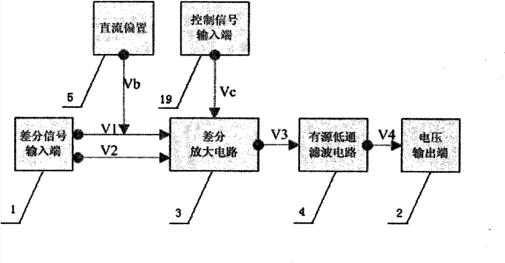
[0018] Example 1, figure 1 A schematic diagram of a differential amplifier circuit that can automatically adjust the magnification of the present invention is shown;

[0019] Such as figure 1 Shown: a differential amplifier circuit that can automatically adjust the magnification, including: differential signal input terminal 1, voltage output terminal 2, DC bias 5, characterized in that the circuit also includes a differential amplifier circuit 3 active filter circuit 4, The connection relationship between each circuit is: the differential signal input terminal 1 receives the differential signal, and transmits the differential signal to the differential amplifier circuit 3 without difference; the DC bias 5 outputs a constant bias voltage signal Vb; the control signal input terminal 19 Receive the control signal output from the control terminal, and transmit the control signal to the differential amplifier circuit, the control signal is used to control the amplification factor...

Embodiment 2

[0028] Example 2, figure 1 A schematic diagram of a differential amplifier circuit that can automatically adjust the magnification of the present invention is shown;

[0029] Such as figure 1 Shown: a differential amplifier circuit that can automatically adjust the magnification, including: differential signal input terminal 1, voltage output terminal 2, DC bias 5, characterized in that the circuit also includes a differential amplifier circuit 3 active filter circuit 4, The connection relationship between each circuit is: the differential signal input terminal 1 receives the differential signal, and transmits the differential signal to the differential amplifier circuit 3 without difference; the DC bias 5 outputs a constant bias voltage signal Vb; the control signal input terminal 19 Receive the control signal output from the control terminal, and transmit the control signal to the differential amplifier circuit, the control signal is used to control the amplification factor...


PUM


Abstract

The invention discloses a differential amplifying circuit capable of automatically adjusting amplification factor, belonging to the differential amplifying circuit. The differential amplifying circuit comprises a differential signal input end 1, a voltage output end 2, a direct current bias 5, a differential amplifying circuit 3 and an active filter circuit 4. The connection relationship is that the differential signal input end 1 receives a differential signal and transfers the differential signal to the differential amplifying circuit 3 with no difference; the direct current bias 5 outputs a constant bias voltage signal Vb; a control signal input end 19 receives a control signal which is output by the control end and transfers the control signal to the differential amplifying circuit 3; the output end of the differential amplifying circuit 3 is connected with the input end of the active filter circuit 4; the amplifying circuit amplifies a useful signal in the difference value of a V1 and a V2; a V3 is processed by the active low-pass filter circuit 4 to obtain a voltage signal V4; the voltage output end 2 transfers the voltage signal V4 which is output by the active low-pass filter circuit 4 with no difference. The differential amplifying circuit has the advantage of detecting a weak differential signal and is capable of automatically changing the amplification factor according to the input differential signal.

Description

technical field [0001] The invention relates to a differential amplifier circuit of a semiconductor integrated circuit, in particular to a differential amplifier circuit capable of automatically adjusting the amplification factor. Background technique [0002] The differential amplifier circuit uses the symmetry and negative feedback of circuit parameters to effectively stabilize the static operating point. It is characterized by amplifying differential mode signals and suppressing common mode signals. It is widely used in the input stage of direct coupling circuits and measurement circuits. However, the structure of the differential amplifier circuit is complex and the analysis is cumbersome. In particular, it has different analysis methods for differential-mode input and common-mode input signals, which is difficult to understand. Therefore, it has always been a difficult point in analog electronic technology. Differential amplifier circuit: According to input and output m...

Claims


Application Information

Patent Timeline
Patent Type & Authority Applications(China)
IPC IPC(8): H03F3/45
Inventor 于华彬王明陶黄正宇
Owner 北京蔚蓝仕科技有限公司
Why Eureka
Try Eureka