

Stave and blast furnace
A stave and blast furnace technology, applied in cooling devices, furnace cooling devices, furnaces, etc., can solve problems such as stave surface loss, and achieve the effects of reducing mechanical wear, preventing wear, and inhibiting wear
- Summary
- Abstract
- Description
- Claims
- Application Information
AI Technical Summary
Problems solved by technology
Method used
Image

Examples
no. 1 Embodiment approach 〕
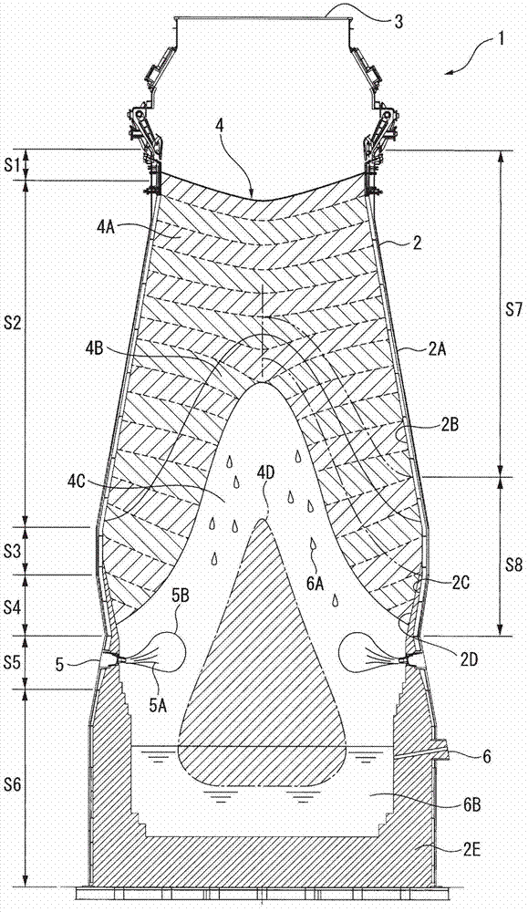
[0058] exist figure 1 Among them, a blast furnace 1 has a cylindrical furnace body 2 constructed on a foundation foundation.
[0059] The furnace body 2 is cylindrical, and is sequentially divided into the furnace mouth part S1, the furnace body part S2, the furnace belly part S3, the furnace waist part S4, the tuyere part S5 and the furnace bottom part S6 starting from the upper gas collection furnace ring beam shell 3. Generally, the inner diameter of the shaft portion S2 gradually expands downward, the inner diameter of the belly portion S3 becomes the largest diameter, and the inner diameter of the belly portion S4 gradually decreases downward.
[0060] In the furnace body 2 , a charging device is usually provided on the ring beam shell 3 of the gas-collecting furnace, and a granular charging material 4 is charged into the blast furnace 1 from the charging device. As the charge 4, an ore-based charge with a particle size in the range of 8 to 25 mm and a coke-based charge ...
no. 2 Embodiment approach 〕
[0124] Figure 11 , Figure 12 and Figure 13 The second embodiment of the present invention is shown.
[0125] The stave 20 for shafts of this embodiment can be used as the stave 2B for shafts in the blast furnace 1 of said 1st Embodiment. The structure of the blast furnace 1 is the same as that of the said 1st Embodiment, and the basic structure of the stave 20 for shafts of this embodiment is the same as the stave 10 for shafts of the said 1st Embodiment. Therefore, description is abbreviate|omitted about the common part with the stave 10 of the said 1st Embodiment, and only a different part is demonstrated below.
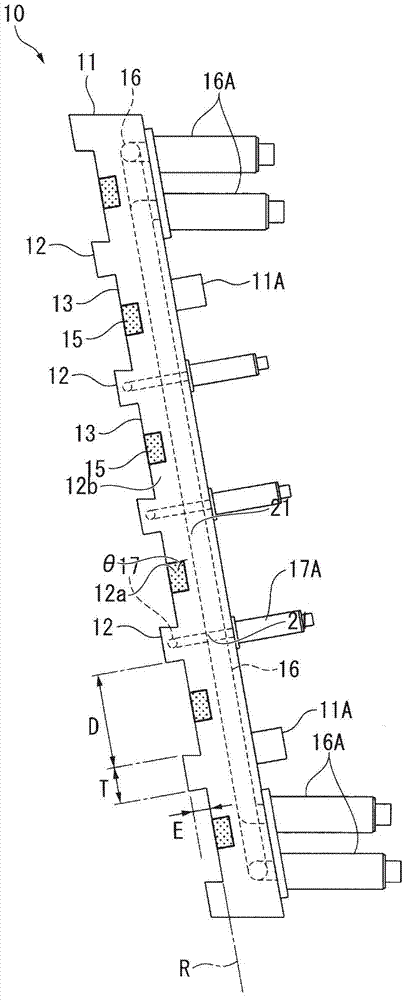
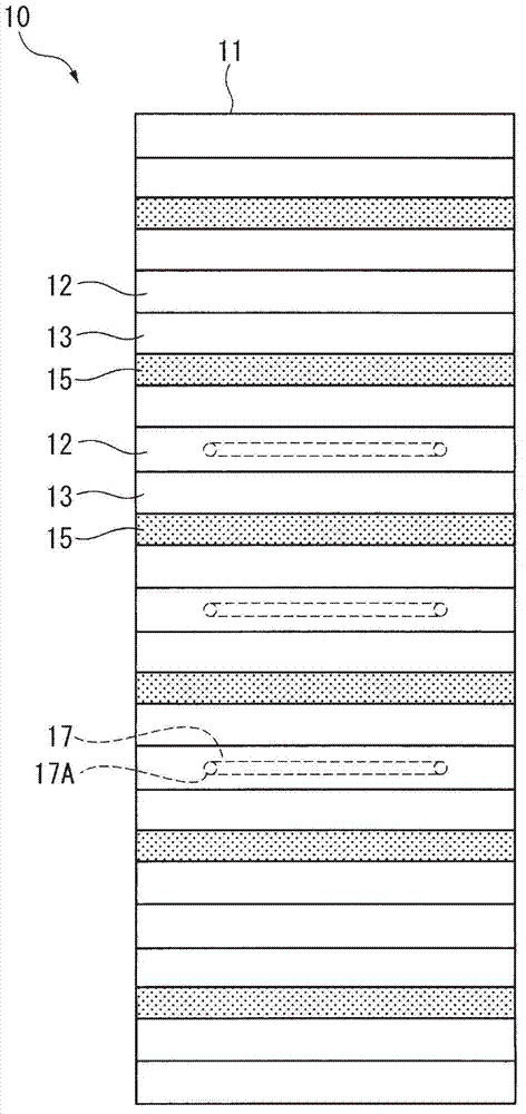
[0126] exist Figure 11 , Figure 12 and Figure 13 Among them, the shaft stave 20 has the same stave main body 11 as the shaft stave 10 of the first embodiment, a bolt support portion 11A, a protrusion 12, a plane 13, a refractory brick 15, a pipeline 16 and Connection port 16A. However, in the stave 10 for shafts of said 1st Embodiment, the piping 17 f...
no. 3 Embodiment approach 〕
[0130] Figure 14 , Figure 15 and Figure 16 The third embodiment of the present invention is shown in .
[0131] The stave 30 for shafts of this embodiment can be used as the stave 2B for shafts in the blast furnace 1 of said 1st Embodiment. The structure of the blast furnace 1 is the same as that of the said 1st Embodiment, and the basic structure of the stave 30 of this embodiment is the same as the stave 10 for shafts of the said 1st Embodiment. Therefore, description is abbreviate|omitted about the common part with the stave 10 for shafts of said 1st Embodiment, and only a different part is demonstrated below.
[0132] exist Figure 14 , Figure 15 and Figure 16 Among them, the stave 30 for shafts has the same stave main body 11, bolt support part 11A, plane 13, refractory brick 15, piping 16, and connection port 16A as the stave 10 for shafts of the said 1st Embodiment. However, the stave 30 for a shaft of this embodiment is not like the stave 10 for a shaft of ...
PUM
 Abstract
Description
Claims
Application Information