Two-stage fuel injection valve for a diesel engine, comprising a solenoid valve and a shuttle valve

A technology for diesel engines and fuel injection valves, applied in fuel injection devices, engine components, machines/engines, etc., can solve problems such as inability to determine injection timing, achieve good combustion performance, optimize spray shape, and improve fuel consumption ratio

Active Publication Date: 2012-11-07
HYUNDAI HEAVY IND CO LTD
View PDF6 Cites 2 Cited by
  • Summary
  • Abstract
  • Description
  • Claims
  • Application Information

AI Technical Summary

Problems solved by technology

[0011] In addition, if Figure 8 In terms of the conventional technology shown, the fuel valve itself cannot determine the injection timing (Timing), but injects according to the predetermined pressure with the help of the previously inflow fuel pressure

Method used


Image

  • Two-stage fuel injection valve for a diesel engine, comprising a solenoid valve and a shuttle valve
  • Two-stage fuel injection valve for a diesel engine, comprising a solenoid valve and a shuttle valve
  • Two-stage fuel injection valve for a diesel engine, comprising a solenoid valve and a shuttle valve

Examples


Embodiment Construction

[0062] The configuration and functions of the embodiments of the present invention will be described in detail below with reference to the accompanying drawings. In addition, in the description of the present invention, when it is judged that a well-known function or a detailed description of a configuration may obscure the gist of the present invention, its detailed description will be omitted.

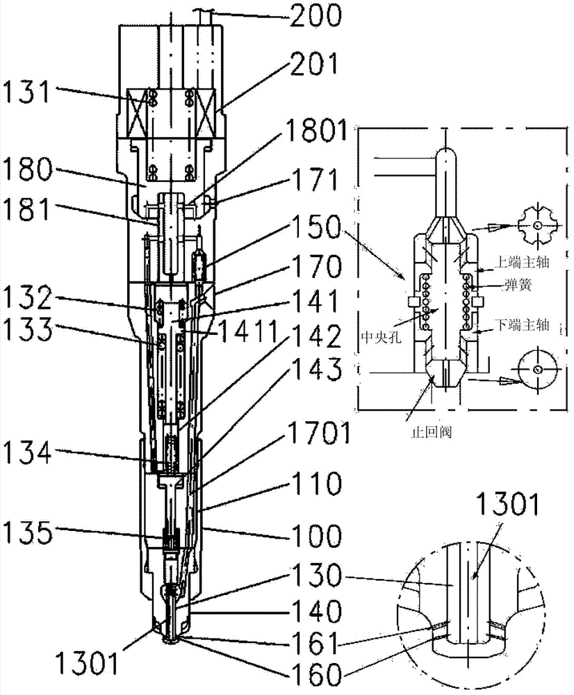
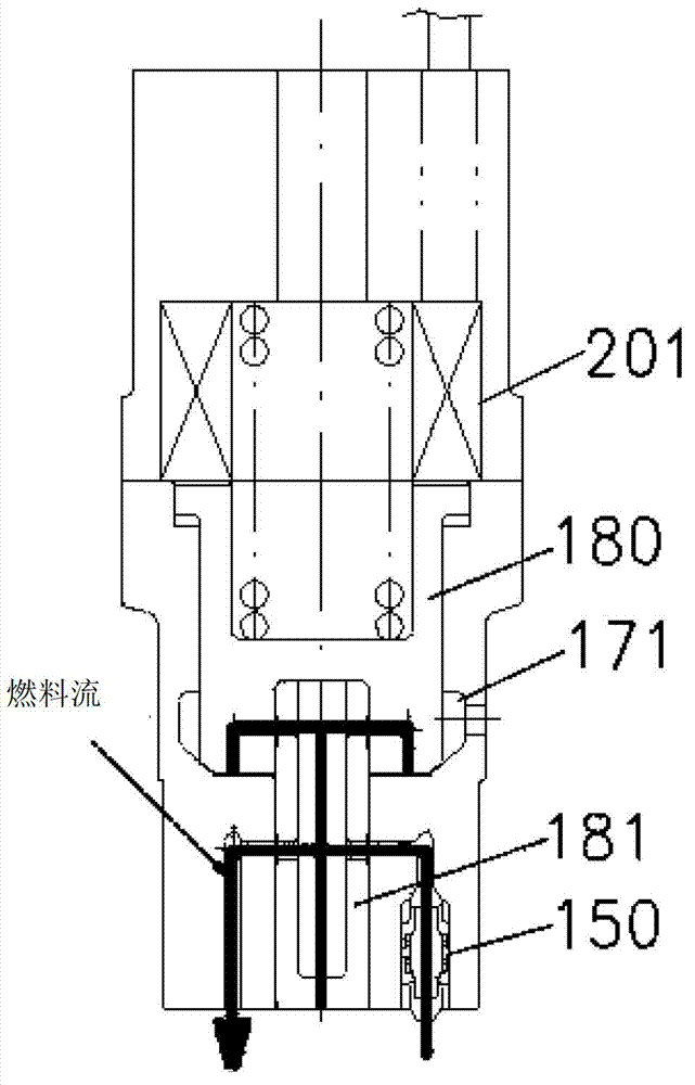
[0063] figure 1 is a schematic cross-sectional view of a fuel injection valve according to the present invention, figure 2 is an embodiment according to the invention of supplying pressure to the booster at low load pressures before solenoid valve activation when not injecting, image 3 It is a cross-sectional schematic diagram of the solenoid valve starting to discharge the relative pressure of the booster. Figure 4 is a schematic cross-sectional view showing an embodiment of the first fuel injection, Figure 5 is a schematic cross-sectional view showing a second fuel injectio...


PUM


Abstract

The present invention relates to a two-stage fuel injection valve for a diesel engine, comprising a solenoid valve and a shuttle valve, wherein an aim of the two-stage fuel injection valve is to carry out a fuel injection method that employs fuel injection timing control within the valve itself, and sequentially injects fuel at low and high pressures, to thereby improve combustion within engine cylinders. According to the present invention, the two-stage fuel injection valve for a diesel engine, comprising a solenoid valve and a shuttle valve, includes: a fuel valve block (110) having a passage (1701), into which fuel oil is fed, defined therein; a nozzle (140) defining a low-pressure nozzle hole (160) and a high-pressure nozzle hole (161) for injecting fuel oil; a needle valve (130) installed within the nozzle for sequentially opening the low-pressure nozzle hole and the high-pressure nozzle hole according to the pressure difference therebetween; a multi-stage pressure booster spindle for pressing the needle valve and raising low-load fuel oil to a high-pressure state, and a needle spring for applying resilient force against the pressure booster spindle; a shuttle valve (150) configured to raise gauge pressure to correspond to the injection pressure of fuel oil supplied to the needle valve, and supply the pressurized fuel oil to the pressure booster spindle; a lifter bush valve (180) for discharging fuel oil through a gap created with a bottom nozzle holder and a fuel discharge hole when a solenoid valve (201) disposed at the top is raised; and said solenoid valve (201) for controlling fuel injection timing by controlling the pressure applied to the top of the lifter bush valve by means of a solenoid valve spring (131).

Description

technical field [0001] The present invention relates to a two-stage fuel injection valve for a diesel engine having a solenoid valve and a shuttle valve, and in particular to a fuel injection valve for changing fuel injection to a cylinder according to the pressure of fuel discharged from a fuel pump in large marine engines and heavy-duty engines The number of injection holes can actively cope with low pressure and high pressure, reduce the amount of residual fuel remaining in the injection flow path after injection, and can obtain a fuel injection valve for diesel engines with better combustion performance and higher fuel consumption ratio. Background technique [0002] Generally, a conventional diesel engine has a needle valve and a spring that open when the pressure of the incoming fuel exceeds the opening pressure (Opening pressure) and close when it falls below the opening pressure (Opening pressure). Therefore, when the high-pressure fuel formed in the fuel pump enters...

Claims


Application Information

Patent Timeline
Patent Type & Authority Applications(China)
IPC IPC(8): F02M45/10F02M61/10F02M61/16
CPCF02M61/08F02M47/027F02M61/045F02M61/10F02M45/12F02M61/042F02M45/04F02M61/182F02M63/004
Inventor 朴得镇金应声金柱泰金钟硕许光哲郑康润河银
Owner HYUNDAI HEAVY IND CO LTD
Why Eureka
Try Eureka