Method for detecting rolling forces during medium plate rolling process

A rolling process and detection method technology, applied in the direction of metal rolling, metal rolling, length measuring device, etc., can solve the problems of restricting rolling production, failure to restore, long maintenance cycle, etc., to achieve continuous production and improve Measuring range, effect of saving purchase cost

Active Publication Date: 2012-11-14
TIANJIN IRON & STEEL GRP
View PDF10 Cites 3 Cited by
  • Summary
  • Abstract
  • Description
  • Claims
  • Application Information

AI Technical Summary

Problems solved by technology

This puts forward quite high requirements on the yield stress of the material used in the detection element. Once the detection element works within the range of plastic deformation, the detection element will be damaged and cannot be recovered. After the damage, the domestic detection and foreign maintenance will require a long maintenance period. , which seriously restricts the rolling production

Method used


Image

  • Method for detecting rolling forces during medium plate rolling process
  • Method for detecting rolling forces during medium plate rolling process
  • Method for detecting rolling forces during medium plate rolling process

Examples


Embodiment 1

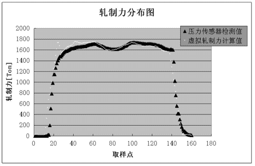
[0022] A method for detecting rolling force in the rolling process of medium and heavy plates, the method realizes the detection of rolling force through indirect detection, and includes the following steps:

[0023] (1) Manually confirm the contact signal of the work roll, which is carried out by deforming the lead wire, and use this signal to trigger recording and store the extension value of the pressing displacement sensor, so as to ensure the successful zeroing of the roll gap calibration;

[0024] (2) Through the data acquisition system (by the main motor control cabinet of the roughing mill), real-time and uninterrupted collection of relevant motor state parameters such as voltage and current, sampling the instantaneous voltage and current of the motor, and passing the collected state parameters through Profibus The field bus is sent to AMS (programmable controller), and then the output work of the motor is calculated according to the formula W=U×I×t and the state parame...

Embodiment 2

[0040] (1) Manually confirm the contact signal of the work roll. The manual confirmation of the work roll contact is carried out in the virtual pressing mode. The virtual pressing mode is based on the successful pressing of the previous time. Calculate the extension value of the displacement sensor at the zero point of the roll gap, and after clicking the compaction button to confirm, record and store the extension value of the displacement sensor to ensure that the roll gap calibration and zero adjustment is successful;

[0041] (2) Through the data acquisition system (by the main motor control cabinet of the roughing mill), real-time and uninterrupted collection of relevant motor state parameters such as voltage and current, sampling the instantaneous voltage and current of the motor, and passing the collected state parameters through Profibus The field bus is sent to AMS (programmable controller), and then the output power of the motor is calculated according to the formula ...


PUM


Abstract

The invention relates to a method for detecting rolling forces during a medium plate rolling process. The method comprises confirming work roll contact signals through manual operation, and confirming that a roll gap calibration is adjusted to be zero; sampling the instantaneous voltage and current of a motor, calculating the power made by the motor in a rolling process through a formula W=U*I*t, and expressing a output torque of the motor with T/, wherein T/=W; filtering the output torque T of the motor, and determining effective work T on the basis that rolling torque effective rolling work T=motor output torque T/-motor rated torque*3%; and calculating the value of a rolling force F through a formula T=2F*B*Arc, wherein the b is a horizontal force arm rate, and the Arc is a contact arc length. According to the method, the value of the rolling force is mapped through observation of the instantaneous voltage and current and calculation of the rolling force arm, the purpose of indirect measurement of the rolling force is achieved, the purchasing expense of a large number of check elements is saved, the measurement range is improved, and the production continuity is guaranteed.

Description

technical field [0001] The invention belongs to the technical field of hot-rolled steel strip production technology in the metallurgical industry, and in particular relates to a method for detecting rolling force during the rolling process of a medium-thick plate. Background technique [0002] The detection link of rolling force in the plate rolling process is the key to the whole process, and the automatic pressing and automatic rolling involved in the basic automation require rolling force detection. At the same time, the self-adaptation of the rolling schedule involved in the process automation also requires the detection and feedback of the rolling force. [0003] At present, for the direct detection method of rolling force, the detection method based on Hooke's law is adopted. According to Hooke's law, within the elastic deformation range of the material, the force and the deformation are proportional, that is, △F=K×△X. In addition, for another detection method of for...

Claims


Application Information

Patent Timeline
Patent Type & Authority Applications(China)
IPC IPC(8): B21B38/08
Inventor 李栋卢建军马金孙智勇黄绍臣
Owner TIANJIN IRON & STEEL GRP
Why Eureka
Try Eureka