Mining system and method of mines
A mining method and mine technology, applied in the field of mining systems, can solve problems such as high labor costs, unstable slopes, and collapse
Inactive Publication Date: 2012-11-14
ZOOMLION ENVIRONMENTAL IND CO LTD
6 Cites 7 Cited by
AI-Extracted Technical Summary
Problems solved by technology
[0003] The latter continuous mining method can basically overcome the low mining efficiency, high labor cost, and complex mining process in the former mining method. It needs to go through drilling, blasting and crushing links, and the mining cost is high. A lot of equipment, high cost of main equipment, high mining investment cost, etc.
However, for the bucket wheel-belt conveyor continuous mining process, there are also the following disadvantages and limitations
Because this kind of mining technology uses ...
Method used
Above-mentioned technical scheme is different from the direct mining method of step surface side end face in the prior art, and the mining method provided by the present invention is to first carry out section-by-section mining on the length direction, and then carry out layer-by-layer mining on the depth direction, i.e. Mining is carried out on the upper surface of the terrace surface, therefore, it will not affect the stability of the slope, and the mining surface is flat, the mining accuracy is high, and through the cooperation of the mining equipment 3 and the transportation equipment 4, continuous mining operations can be carried out , high work efficiency, low cost, and will not affect the stability of the slope of the mine, and will not cause safety problems such as slope collapse that may be caused by directly mining the side and end faces of the steps of the mine, thereby avoiding affect the safety of construction.
In a preferred embodiment of the present invention, as shown in Figure 4, the mining equipment 3 includes a walking mining machine 31, the walking mining machine 31 is provided with a milling drum 311 capable of milling and crushing operations , and set the milling drum 311 in contact with the mining face 1 . Specifically, the walking mining machine 31 includes two sets of crawler belts 312 arranged front and back to realize the walking of the equipment, and the milling drum 311 is arranged between the two sets of crawler belts 312 and contacts the mining face 1, so as to realize the operation of the mining face 1. Precise and stable mining. In a preferred embodiment of the present invention, the provided walking mining machine 31 is a crawler-type walking machine integrating mining and walking. The millin...
Abstract
The invention discloses a mining method of mines. The mining method comprises an obtaining mining step of mineral aggregates and a transportation step of transporting the mineral aggregates. In the mining method, the mines are divided into a plurality of mining faces in the depth direction, and each mining face is divided into a plurality of mining sections in the length direction. Mining operation is carried out in the width direction of a first mining section, and then mining of the next mining section is carried out. When mining of the mining face on a first layer is completed, mining of a next mining face on the lower layer is carried out. The invention further provides a mining system of mines capable of completing the mining method. By means of the technical scheme, the mining method is a layer-and-layer mining method, continuous mining of the mines can be completed through the mining system, and stability of side slopes cannot be influenced.
Application Domain
Open-pit miningPropulsion +1
Technology Topic
MineralogyDepth direction
Image
Examples
- Experimental program(1)
Example Embodiment
[0049] The specific embodiments of the present invention will be described in detail below with reference to the accompanying drawings. It should be understood that the specific embodiments described herein are only used to illustrate and explain the present invention, and not to limit the present invention.
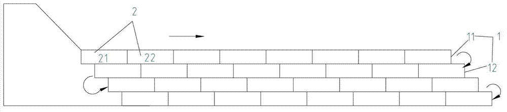
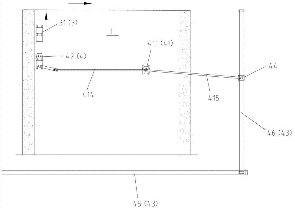
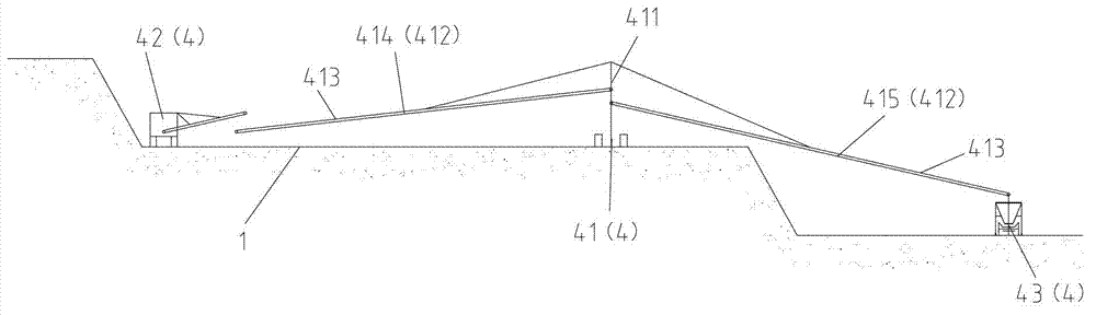
[0050] In the present invention, in the case of no explanation to the contrary, the orientation words used such as "up, down, left, right" are figure 1 , image 3 , Figure 4 , Figure 5 with Image 6 The drawing direction shown is defined based on the reference, and the following "length direction", "width direction" and "depth direction" are three-dimensional definitions performed under the overall mine, specifically, figure 1 Among them, the "length direction" is the left and right direction, the "depth direction" is the up and down direction, and the "width direction" is the direction inside and outside the paper. In addition, other locating words are described in conjunction with the specific drawings. It should be noted that these locating words are only used to illustrate the present invention, especially the definitions of "length direction" and "width direction" are only relative definitions and are not used to limit the present invention. .
[0051] Such as Figure 1 to Figure 6 As shown, the present invention provides a mine mining method and a mining system for completing the mining method, wherein figure 1 As shown, the mining method provided by the present invention includes a mining step of using mining equipment 3 to obtain mineral materials and a transportation step of using transportation equipment 4 to transport mineral materials, and in the mining method, the mine is divided into multiple mining in the depth direction. And divide each mining surface 1 into multiple mining sections 2 in the length direction; and the mining system first performs mining operations in the width direction of the first mining section 21, and when the first mining section 21 is completed After mining, as shown by the straight arrow, the next mining section 22 that is connected to the first mining section 21 is mined; when the mining of the first mining surface 11 is completed, the mining system will proceed with the first mining surface 11. The mining of the adjacent lower mining surface 12; among them, preferably, in order to complete the mining of the mine most efficiently, when the mining of the first mining surface 11 is completed, the mining of the adjacent lower mining surface 12 is directly entered, and so on, in figure 1 , The mining process in the depth direction is carried out in an S-shaped manner as shown by the curved arrow, so as to complete the mining of each layer of the mine in the most efficient manner. In the same way, although not shown, in the width direction of the mining surface 1, after the first mining section 21 is completed, it is also preferable to directly enter the adjacent next mining section 22 for widthwise mining. The mining process on each mining face 1 is also S-shaped to complete the mining operation most efficiently. In addition, in order to continuously complete the above-mentioned mining process, in the mining operation of the mining method provided by the present invention, the transportation step is performed at the same time as the mining step, that is, the mining equipment 3 and the transportation equipment 4 can cooperate with each other to continuously complete the mine Mining.
[0052] The above technical solution is different from the direct mining method on the side end of the step surface in the prior art. The mining method provided by the present invention is to first perform segment mining in the length direction, and then perform layer mining in the depth direction, that is, on the step surface. Mining is carried out on the upper surface of the mine, so it will not affect the stability of the slope, and the mining surface is flat, with high mining accuracy, and through the cooperation of the mining equipment 3 and the transportation equipment 4, continuous mining operations can be carried out, and the work efficiency High, low cost, and will not affect the stability of the mine slope, and there will be no safety issues such as slope collapse that may be caused by directly mining the step side end face of the mine, thereby avoiding affecting the construction Security.
[0053] It should be noted that the description of mining section 2 is added to the present invention for the convenience of explaining the mining method of section mining and layer mining of the present invention. figure 1 Among them, the size of each mining section 2 (unit mining width and mining depth in the length direction and depth direction of the mining surface) depends on the specification and form of the mining equipment, that is, it is determined by the unit mining volume of the mining equipment. For example, in the preferred embodiment of the present invention, when the milling drum of the following walking mining machine is used for mining, usually the one-time mining width is the width of the milling drum (such as about 2m), and the mining depth is the milling depth of the milling drum ( For example, about 0.02m). That is, the unit mining volume of the walking mining machine is (2×0.02) m 2 , Which is figure 1 The specifications of each small grid. This description is only used to illustrate the present invention, not to limit the present invention. In addition, there are many implementations that can implement the above technical solutions, such as the types and arrangements of mining equipment and transportation equipment, etc. For the convenience of describing the present invention, only the preferred implementations are introduced here.
[0054] Among them, in order to make the present invention more applicable, it is different from the blasting (usually used in hard rock) or excavation (usually used in soft rock) used in the prior art. Preferably, the mining method provided by the present invention In the process, the mining equipment 3 used can directly perform milling operations on the mining face 1 to obtain mineral materials. Through this milling operation, the mining equipment 3 can correspond to the different lithology (soft and hard) of the mine, so that the mining efficiency and continuity are good, and the mining accuracy is high. Among them, it is more preferable that the mining equipment 3 can crush the obtained mineral material at the same time as the milling operation, so as to reduce the particle size of the mineral material. Therefore, there is no need to separately set up crushing machinery for crushing, but directly enter the transportation equipment for outbound transportation, which greatly reduces mining costs and improves operation continuity.
[0055] In a preferred embodiment of the present invention, such as Figure 4 As shown, the mining equipment 3 includes a walking mining machine 31, and the walking mining machine 31 is provided with a milling drum 311 capable of milling and crushing operations, and the milling drum 311 is set in contact with the mining surface 1. Specifically, the walking mining machine 31 includes two sets of crawlers 312 arranged front and rear to realize the walking of the equipment, and the milling drum 311 is arranged between the two sets of crawlers 312 and is in contact with the mining surface 1, so as to achieve the Accurate and stable mining. In a preferred embodiment of the present invention, the walking mining machine 31 provided is a crawler walking machine integrating mining and walking. The milling drum is equipped with tungsten carbide tipped picks. When the milling drum is spin-on, the spirally arranged milling tools cut into the ore body in turn, and the milled mineral particles are discharged before the drum shell. With the movement of the drum, it is further broken to form loose mineral materials with a certain granularity. The particle size of the mineral material can reach <300mm, which fully meets the subsequent transportation conditions. After mining by the walking mining machine 31, the mineral materials will be scattered on the mining surface to form a loose mineral material layer with a certain mining width and mining depth. In order to facilitate the transportation of mineral materials by the transportation equipment 4.
[0056] By using the walking mining machine 31, there is no need to set up additional equipment for blasting, excavation, and crushing, which greatly saves construction costs. In addition, by using the walking mining machine 31, the selective mining capacity in the mining process is increased, and it is possible to carry out economical mining of thin mining areas in time, realize selective mining to the greatest extent, and increase the mining rate of the mine. The above-mentioned walking mining machine 31 can be manufactured separately, or can be obtained by modifying equipment such as road milling machine, milling machine, etc. The above-mentioned milling drum is a common component in the field, and besides being installed between the crawlers, it can also The cantilever structure is installed in the front and rear of the walking mining machine 31. For the walking mining machine 31, various deformations that can be imagined by those skilled in the art, as long as they can meet the purpose of the present invention, fall into the present invention. In the scope of protection.
[0057] In order to cooperate with the mining equipment 3 provided by the present invention to realize the continuity of mining, first transfer the obtained mineral material outside the mining surface, and preferably, simultaneously transport the mineral material transferred outside the mining surface. To achieve this goal, first of all, in the preferred embodiment of the present invention, such as figure 2 with image 3 As shown, the transportation equipment 4 includes a walking transfer machine 41 that transfers mineral materials to the outside of the mining surface 1. The walking transfer machine 41 can cooperate with the mining equipment 4 (walking mining machine 31) to travel, and specifically, such as Image 6 As shown, the walking transfer machine 41 includes a fuselage body 411 and a transfer boom 412 mounted on the fuselage body 411. The transfer boom 412 is provided with a transfer conveyor belt 413 for conveying minerals, and a transfer boom is provided. 412 extends from the current mining section 2 (that is, the current mining point) to the outside of mining surface 1 (or the location of the mining surface that is not the current mining point), so as to realize the transfer of the obtained mineral material to the outside of the mining section to facilitate the mining of the mineral material. Foreign transport. More specifically, the transfer boom 412 includes a front boom 414 and a rear boom 415 respectively rotatably installed on both sides of the fuselage body 411. The front boom 414 and the rear boom 415 respectively have a transfer conveyor 413, and the front boom 414 The discharge end corresponds to the feed end of the rear boom 415, so that the rear boom 415 can receive the mineral material from the front boom 414. This makes the reloading process of mineral materials more stable and reliable. In the preferred embodiment of the present invention, the walking transfer machine 41 is a crawler-type walking transfer machine. The front and rear booms 414 and 415 can be pitched and rotated. The mineral material is transferred from the mining point on the mining surface 1 to the outside of the mining surface 1 through the transfer conveyor belt arranged on the boom. The pitch and rotation functions of the front and rear booms 414 and 415 can ensure the smooth transfer of mineral materials when the transfer machine is in different positions. Under the cost permitting, the greater the pitch and rotation of the boom, the better, and the more convenient it is to mine Equipment 3 cooperates.
[0058] In order to facilitate the loading of mineral materials on the forearm frame 414 of the walking transfer machine 41, preferably, as Figure 5 As shown, the transportation equipment 4 includes a walking ore loading machine 42 that loads mineral materials to the first end of the transfer conveyor 413. Specifically, a collection device 421, a conveyor belt 422 connected to the collection device 421, and a discharge conveyor arm 423 connected to the conveyor belt 422 are provided on the walking loader 42, and the discharge conveyor arm 423 is rotatably installed on the walking type ore loading machine 42. In a preferred embodiment of the present invention, the ore loading machine is a crawler-type walking machine that integrates loading, reloading, and walking. It relies on a collection device 421 (such as a star wheel collection device) at its front end to collect the mineral material mined by the mining equipment 3 (walking mining machine 31), and transfers the mineral material to the unloading conveyor belt through a conveyor belt 422 on. The unloading conveyor arm 423 can perform a ±90° rotation movement, which can continuously and smoothly transfer the mineral material to the next link (walking transfer machine 41).
[0059] For maximum efficiency mining, preferably, such as figure 2 with image 3 As shown, the above-mentioned walking loader 42 and walking transfer machine 41 can be matched with the mining equipment 3, wherein preferably, the walking loader 42, the walking transfer machine 41 and the mining equipment 3 move synchronously. Specifically, such as figure 2 As shown, during the mining process, the walking loader 42 follows the mining equipment 3 (walking mining machine 31) to synchronously travel in the width direction of the mining surface 1 and perform mineral loading operations. The walking transfer machine 41 and the walking loader 42 can be aligned and arranged on the mining surface 1 and move synchronously along the mining direction. The material receiving point of the transfer conveyor belt 413 of the forward transfer boom 414 is placed in the walking loading ore. Below the unloading point of the unloading conveyor arm 423 of the machine 42, and then the unloading point of the transfer conveyor belt 413 of the transfer arm 415 is placed on the following mineral material conveyor 43 which transports mineral materials outwards, To ensure that the material can be accurately received and discharged.
[0060] In the aforementioned coordination process of mining and transportation, a separate walking loader 42 is used to load the mineral material on the walking transfer machine 41, and in actual work, various other things that those skilled in the art can think of can be used. For example, according to the humidity of the mineral material, the structure of the unloading conveyor belt is directly installed at the rear of the walking mining machine, or the mining equipment is directly selected to collect and transfer, such as milling in the walking mining rack 31 provided by the present invention. After the drum 311 is equipped with a collection device and a conveying device, the mineral material milled and broken by the milling drum 311 can be directly transferred to the walking transfer machine 42. In the field of mining equipment, suitable equipment can be arbitrarily selected to replace the equipment in the preferred embodiment of the present invention. For example, the walking loader can be replaced with a slag raking machine that can meet the purpose of the present invention and other common collection and transfer equipment. As long as it is within the concept of the present invention, such replacements fall within the protection scope of the present invention.
[0061] After the reloading of the mineral material is completed, the mineral material needs to be transported at the same time to complete the continuous mining of the entire mine. Therefore, it is preferable that the transportation device 4 includes a mineral material conveyor 43 for transporting the mineral material. The specific layout of the mineral material conveyor 43 needs to be determined in conjunction with the actual situation of the mine itself. A separate conveyor can be used for transportation, or multiple conveyors that cooperate with each other can be used for transportation. The present invention does not limit this deformation. .
[0062] In such figure 2 with image 3 In the preferred embodiment shown, a first conveyor 46 is included in the mineral material conveyor 43, and the main body 461 of the first conveyor 46 is arranged along the width direction of the mining surface 1 and on the first conveyor 46 A receiving hopper 44 moving along the main body 461 is provided, and the receiving hopper 44 is provided corresponding to the second end of the walking transfer machine 41 to receive and transport mineral materials. Since the mining operation of the mining equipment 3 (walking mining machine 31) is carried out in the width direction of the mining surface, the first conveyor 46 of the main body 461 arranged along the width direction of the mining surface 1 can well match the mining equipment 3 ( The walking type mining machine 31), the walking type ore loading machine 42 and the walking type transfer machine 41 move synchronously, and the receiving hopper 44 on it ensures accurate and stable transportation of the mineral material. Of course, the purpose of the present invention can also be achieved by directly using conveying equipment such as belt conveyors without using the receiving hopper 44, which will not be repeated here. In addition, under certain working conditions, a second conveyor 45 needs to be provided, and the feed end of the second conveyor 45 corresponds to the discharge end of the first conveyor 46, such as figure 2 As shown, the second conveyor 45 is arranged along the length direction of the mining surface 1, that is, perpendicular to the arrangement direction of the first conveyor 46, so as to transport the mineral material out in cooperation with each other. In the specific working process, after receiving the mineral material transferred by the walking transfer machine 41, the force receiving bucket 44 moves along the main body 461 of the first conveyor 46 to the receiving point of the second conveyor 45 to transfer the mineral material. Transfer to the second conveyor 45, so as to realize the export of mineral materials.
[0063] In the above transportation process, since the mining surface of an open-pit mine is usually very large, for example, thousands of meters, the mineral material conveyor 43 is generally no longer easy to move after being arranged. Because the layout of the first conveyor 46 is usually related to the mining surface, When this mining surface is mined for the next mining surface, the first conveyor needs to be moved. The second conveyor 45 only needs to be able to receive the mineral material of the first conveyor 46, and usually does not move after it is arranged.
[0064] So far, the mining process in the preferred embodiment provided by the present invention is completed. In summary, it can be obtained that the mining method and mining system provided by the present invention realize continuous mining of the mine without affecting the safety of construction, without requiring separate blasting operations and crushing operations, and lower cost. Mainly through the synchronous walking of the walking mining machine 31 (mining equipment 3), walking mining loader 42 (transporting equipment 4) and walking transfer machine 41 (transporting equipment 4), and combined with the mineral material conveyor 43 (transporting equipment 4) Synchronous work can complete the continuous mining work of the entire mine. Among them, the layout of each equipment is compact and reliable, and the capabilities are matched with each other, realizing the continuous construction of continuous mining and transportation in the mine. In addition, all the equipment involved in the present invention can be domestically produced equipment. Through the mining method provided by the present invention, the dependence on imported equipment such as bucket wheel excavators is reduced, and the mining cost of the mine is lower. Therefore, the mine mining method and system provided by the present invention have high practicability and promotion value.
[0065] The preferred embodiments of the present invention are described in detail above with reference to the accompanying drawings. However, the present invention is not limited to the specific details in the above-mentioned embodiments. Within the scope of the technical concept of the present invention, many simple modifications can be made to the technical solutions of the present invention. These simple modifications all belong to the protection scope of the present invention.
[0066] In addition, it should be noted that the various specific technical features described in the above-mentioned specific embodiments can be combined in any suitable manner without contradiction. In order to avoid unnecessary repetition, the present invention is The combination method will not be explained separately.
[0067] In addition, various different embodiments of the present invention can also be combined arbitrarily, as long as they do not violate the idea of the present invention, they should also be regarded as the content disclosed in the present invention.
PUM


Description & Claims & Application Information
We can also present the details of the Description, Claims and Application information to help users get a comprehensive understanding of the technical details of the patent, such as background art, summary of invention, brief description of drawings, description of embodiments, and other original content. On the other hand, users can also determine the specific scope of protection of the technology through the list of claims; as well as understand the changes in the life cycle of the technology with the presentation of the patent timeline. Login to view more.