Hydraulic oil cooling device of coal mining machine

A cooling device and hydraulic oil technology, which is applied in fluid pressure actuation devices, mechanical equipment, fluid pressure actuation system components, etc., can solve problems such as large water consumption, system paralysis, and difficulty in cleaning, and achieve increased contact area, System stability and space-saving effect

Inactive Publication Date: 2012-11-14
JIANGSU ZHONGJI MINE EQUIP
View PDF6 Cites 5 Cited by
  • Summary
  • Abstract
  • Description
  • Claims
  • Application Information

AI Technical Summary

Problems solved by technology

[0004] The copper tube cooler installs the copper tube in the oil tank, and the cooling water flows through the tube to take away the heat generated in the oil. This kind of cooler has low cost, but the heat exchange efficiency is low, the volume is large, and the water consumption is large.
In the plate-fin cooler, the cooling tube is covered with multiple heat-dissipating fins made of good heat-conducting materials to increase the heat-dissipating area. There will be a pipe burst and the whole system will be paralyzed. In addition, the structure is relatively large and cumbersome, and it will take up too much space in the shearer, which is not conducive to piping and wiring.

Method used


Image

  • Hydraulic oil cooling device of coal mining machine
  • Hydraulic oil cooling device of coal mining machine
  • Hydraulic oil cooling device of coal mining machine

Examples


Embodiment Construction

[0021] The present invention will be described below in conjunction with the accompanying drawings and embodiments.

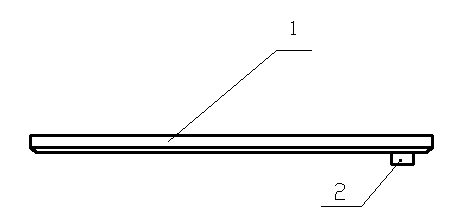
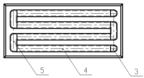
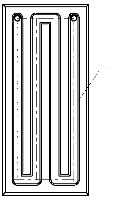
[0022] Such as Figure 1 to Figure 11 As shown, a shearer hydraulic oil cooling device of the present invention includes six cooling plates assembled and welded together up, down, left, right, front, back, and front. The cooling plate includes a bottom plate 1, a joint seat 2, an end plate 3, a strip plate 4 and a pressure plate 5, wherein the end plate 3, the strip plate 4 and the pressure plate 5 are respectively welded on the bottom plate 1, the pressure plate 5 is connected with it at the corner of the strip plate 4, the end plate 3 is connected with the two ends of the strip plate 4, and then The joint seat 2 is welded at the corresponding position opposite to the end plate 3 to form a serpentine water channel, and the number and size of each part are determined according to the size of the bottom plate 1 of each cooling plate of the fuel tank.

[0023] T...


PUM


Abstract

The invention discloses a hydraulic oil cooling device of coal mining machine. The hydraulic oil cooling device comprises six cooling plates which are arranged around (up and dowm, right and left, and front and back) and are welded together, wherein the cooling plate comprises a bottom plate, a joint seat, an end plate, a strip plate and a pressing plate, wherein the end plate, the strip plate and the pressing plate are respectively welded on the bottom plate; the pressing plate is connected with the strip plate at a corner of the strip plate; the end plate is connected with two ends of the strip plate; and the joint seat is welded at a corresponding position opposite to the end plate. Compared with the prior part, the cooling device provided by the invention is embedded in various cooling plates of an oil tank by a serpentine waterway; water in the waterway flows fast; and area of the oil contacting cooled water is increased so as to achieve the purpose of fully cooling at high efficiency; furthermore, various plates are connected with each other through the joint seat on the end plate to form a cooled water circulating loop with water source of a cold water pump station, so that entire oil tank composes the hydraulic oil cooling device by self, thereby removing a traditional cooler, stabilizing systems and saving space.

Description

technical field [0001] The invention relates to a coal mining machine hydraulic oil cooling device, in particular to a water cooling device provided in the coal mining machine oil tank itself. Background technique [0002] When the shearer hydraulic system works normally, it will generate heat, which will cause the oil temperature to be too high for a long time, causing the oil to deteriorate rapidly, and at the same time, the oil viscosity will decrease and the system efficiency will decrease. Therefore, keeping the oil temperature within a certain range is a necessary condition to ensure the normal operation of the hydraulic system, and generally a cooling device must be installed. [0003] At present, the cooler is the most commonly used temperature control facility. The commonly used cooling methods are water cooling, air cooling and ammonia cooling. Due to the unique shape and compact space of the shearer, it is mainly water-cooled. The most commonly used water cooler...

Claims


Application Information

Patent Timeline
Patent Type & Authority Applications(China)
IPC IPC(8): F15B21/04
Inventor 董璇璇罗兴臣杨硕
Owner JIANGSU ZHONGJI MINE EQUIP
Why Eureka
Try Eureka