
Chirp pulse time delay estimation method for non-uniform sampling

A non-uniform sampling, pulse delay technology, applied in radio wave measurement systems, instruments, etc., can solve the problems of Chirp pulse delay estimation ambiguity, limited sampling frequency, frequency shift estimation ambiguity, etc., to reduce the amount of calculation and complexity. low system complexity, and the effect of reducing the sampling rate

Inactive Publication Date: 2012-11-14
ANHUI UNIV OF SCI & TECH
View PDF2 Cites 14 Cited by
  • Summary
  • Abstract
  • Description
  • Claims
  • Application Information

AI Technical Summary

Problems solved by technology

[0004] The Chirp pulse delay estimation method based on the fractional Fourier transform is to estimate the pulse delay by estimating the Doppler frequency shift caused by the signal delay, and it is limited by the sampling frequency when sampling uniformly.
When the pulse delay is too large and the frequency shift caused by the delay exceeds the sampling frequency of the signal, frequency aliasing will occur in the fractional Fourier domain, resulting in ambiguity in frequency shift estimation, which in turn makes the delay estimation of Chirp pulses ambiguous

Method used


Image

  • Chirp pulse time delay estimation method for non-uniform sampling
  • Chirp pulse time delay estimation method for non-uniform sampling
  • Chirp pulse time delay estimation method for non-uniform sampling

Examples


Embodiment Construction

[0033] The technical solution of the present invention will be further explained below in conjunction with the accompanying drawings and embodiments.

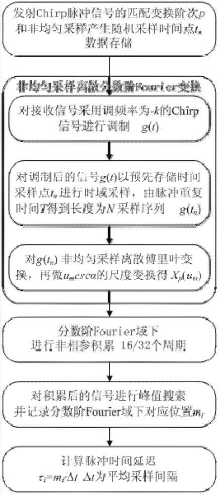
[0034] Non-uniform sampling Chirp pulse delay estimation method, the implementation flow chart is attached figure 2 shown. First, according to the modulation frequency k (kp , select the transformation order p = 2arccot(-k) / π of the fractional Fourier transform, and generate a random sampling time point t according to the additive non-uniform sampling time n , and store the corresponding data;

[0035] On this basis, concrete realization steps of the present invention are as follows:

[0036] 1) For the echo signal of the received linear frequency modulation pulse system radar, the Chirp pulse signal exp{-jπkt with modulation frequency of -k is used 2} to modulate, and obtain the modulated signal g(t).

[0037] 2) Convert the modulated signal g(t) to the pre-stored time point t n Perform non-uniform sampling in the time d...


PUM


Abstract

The invention discloses a Chirp pulse time delay estimation method for non-uniform sampling. The method comprises the following steps of transmitting the matched transform order p of a Chirp pulse signal and a random sampling time point tn generated by non-uniform sampling, and performing data storage; modulating a received signal by adopting a Chirp pulse signal of which the modulating frequency is -k to obtain a modulated signal g(t); performing time-domain sampling on the g(t) with tn to obtain a sampling sequence g(tn), performing non-uniform sampling discrete Fourier transform on g(tn), then performing scale transform on umcscalpha to obtain Xp(um), and performing non-coherent integration on the amplitude (the absolute value of Xp(um)) of a signal under a fractional order Fourier domain; and performing peak search on the integrated signal, recording a corresponding position mi under the fractional order Fourier domain, and further calculating pulse time delay taui=mi.deltat. According to the method, the problem of time delay fuzziness since frequency deviation is larger than a signal sampling rate due to excessive pulse time delay under a uniform low-speed sampling condition can be solved effectively.

Description

technical field [0001] The technology relates to a non-uniform sampling Chirp pulse time delay estimation method, which belongs to the field of radar signal processing. Background technique [0002] Chirp pulse system radar uses Chirp pulse signal (also known as chirp signal), which can increase the transmission power at a lower peak power by increasing the pulse width, and obtain a longer detection distance and higher distance resolution , to overcome the contradiction between detection distance and distance resolution, it is currently the most widely used and most mature pulse compression system radar in engineering applications. [0003] The Chirp signal can be regarded as an extended form of the sine-cosine function (the tuning frequency is 0, that is, it degenerates into a sine-cosine function), and the Chirp function family is also a generalized form of the Fourier transform—a fractional Fourier transform (FRFT). Group basis functions, the Chirp signal has the form of...

Claims


Application Information

Patent Timeline
IPC IPC(8): G01S7/41G01S7/36
Inventor 李昕
Owner ANHUI UNIV OF SCI & TECH
Learn More