
Liquid crystal display device, and frame unit and liquid crystal panel alignment method thereof

A technology of a liquid crystal display device and a liquid crystal panel, which is applied in the field of liquid crystals, can solve the problems of increasing the thickness of the frame of the liquid crystal display device, the inability to realize the design of the ultra-narrow frame, and the unfavorable automatic assembly of the liquid crystal display device, etc., so as to realize the ultra-narrow frame and realize automation Assembly, thickness reduction effect

Active Publication Date: 2012-11-14
TCL CHINA STAR OPTOELECTRONICS TECH CO LTD
View PDF9 Cites 21 Cited by
  • Summary
  • Abstract
  • Description
  • Claims
  • Application Information

AI Technical Summary

Problems solved by technology

[0003] However, the retaining wall structure on the plastic frame will increase the thickness of the frame of the liquid crystal display device, and cannot realize the design of the ultra-narrow frame
At the same time, the plastic frame of the backlight module cannot well realize the precise alignment of the liquid crystal panel, which is not conducive to the automatic assembly of the liquid crystal display device

Method used


Image

  • Liquid crystal display device, and frame unit and liquid crystal panel alignment method thereof
  • Liquid crystal display device, and frame unit and liquid crystal panel alignment method thereof
  • Liquid crystal display device, and frame unit and liquid crystal panel alignment method thereof

Examples


Embodiment 1

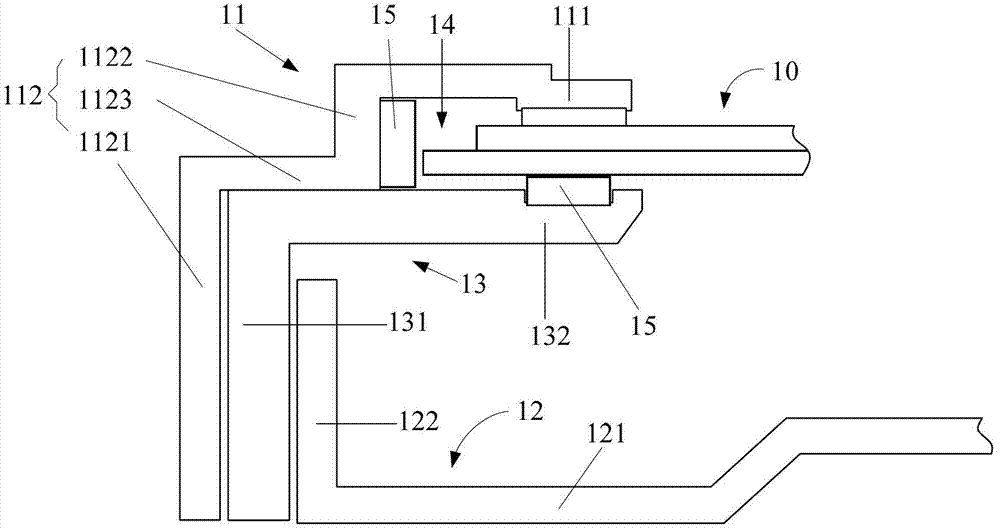
[0022] Example 1, please refer to figure 1 , figure 1 It is a partial structural schematic diagram of a liquid crystal display device using a frame unit according to an embodiment of the present invention.

[0023] In this embodiment, the liquid crystal display device includes a liquid crystal panel 10 and a frame unit, and the frame unit includes but not limited to a front frame 11 and a back panel assembly 12 .

[0024] Specifically, there may be one or more front frames 11 , which include a connected cover plate 111 and a retaining wall 112 . The cover plate 111 abuts against the upper surface of the liquid crystal panel 10 , and its bottom surface can be arranged parallel to the upper surface of the liquid crystal panel 10 to achieve a better fixing effect. The retaining wall 112 may be perpendicular to the cover plate 111, and the retaining wall 112 elastically abuts against the side of the liquid crystal panel 10. Further, the retaining wall 112 may include a first ret...

Embodiment 2

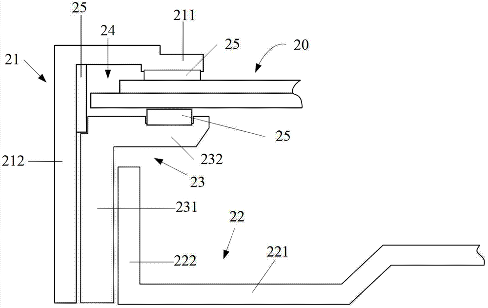
[0030] Example 2, please refer to figure 2 , figure 2 It is a partial structural schematic diagram of a liquid crystal display device adopting another embodiment of the frame unit of the present invention.

[0031] In this embodiment, the liquid crystal display device includes a liquid crystal panel 20 and a frame unit, and the frame unit includes but not limited to a front frame 21 and a back panel assembly 22 .

[0032] The front frame 21 includes a cover plate 211 and a retaining wall 212 which can be vertically arranged, and the back plate assembly 22 includes a bottom plate 221 and a side plate 222 which are connected. It should be pointed out that: the difference between the second embodiment and the first embodiment is that the retaining wall 212 in the second embodiment is arranged parallel to the vertical part 231 and the side plate 222, and does not form a ladder shape as in the first embodiment, that is to say, the retaining wall 212 The wall 212 is not configur...


PUM


Abstract

The embodiment of the invention discloses a liquid crystal display device and a frame unit thereof. The frame unit comprises a front frame and a backplate assembly, wherein the front frame comprises a cover plate and a retaining wall which are connected; the cover plate is elastically abutted with the upper surface of a liquid crystal panel of the liquid crystal display device; the retaining wall is elastically abutted with the side edge of the liquid crystal panel; the backplate assembly comprises a bottom plate and a side plate which are connected; the bottom plate is used for supporting the optical part of the liquid crystal display device; and the side plate is matched with the retaining wall so as to support the liquid crystal panel. The invention further discloses a liquid crystal panel alignment method of the liquid crystal display device. According to the invention, the frame thickness of the liquid crystal display device can be effectively reduced, the production cost can be lowered, and the automatic assembling of the liquid crystal display device can be realized.

Description

technical field [0001] The invention relates to the field of liquid crystals, in particular to a liquid crystal display device and a frame unit thereof, and also to a liquid crystal panel alignment method. Background technique [0002] In the prior art, liquid crystal display devices are mostly assembled by placing the liquid crystal panel on the backlight module, the retaining wall structure on the plastic frame of the backlight module is used to abut against the liquid crystal panel in the horizontal direction, and the cover plate on the plastic frame The structure is used to fix the liquid crystal panel in the vertical direction, and the positioning of the liquid crystal panel is realized through the combined use of the retaining wall structure and the pressing structure. [0003] However, the retaining wall structure on the plastic frame will increase the thickness of the frame of the liquid crystal display device, so that the ultra-narrow frame design cannot be realized...

Claims


Application Information

Patent Timeline
Patent Type & Authority Applications(China)
IPC IPC(8): G02F1/13H05K7/18
CPCG02F1/1333G02F1/133308G02F1/133314G02F1/13332G02F1/133322
Inventor 郭仪正萧宇均阙成文张庞岭李德华
Owner TCL CHINA STAR OPTOELECTRONICS TECH CO LTD
Learn More