
Precise locating detecting method for truss girder

A detection method, truss beam technology, applied in position/direction control, measuring device, surveying and navigation, etc., to achieve powerful functions, high precision, and the effect of height detection

Active Publication Date: 2012-11-14
CHINA RAILWAY 23RD CONSTR BUREAU LTD +1
View PDF5 Cites 15 Cited by
  • Summary
  • Abstract
  • Description
  • Claims
  • Application Information

AI Technical Summary

Problems solved by technology

[0003] The purpose of the present invention is to overcome the shortcomings of existing methods that cannot effectively and accurately detect truss beams with small bending radii and various linear structures, and provide a method with high efficiency, high precision and reliable results. An accurate in-position detection method for truss beams, especially suitable for in-position detection of truss beams with small bending radii and various linear structures

Method used


Image

  • Precise locating detecting method for truss girder
  • Precise locating detecting method for truss girder
  • Precise locating detecting method for truss girder

Examples


Embodiment Construction

[0034] The present invention will be further described in detail below in conjunction with test examples and specific embodiments. However, it should not be understood that the scope of the above subject matter of the present invention is limited to the following embodiments, and all technologies realized based on the content of the present invention belong to the scope of the present invention.

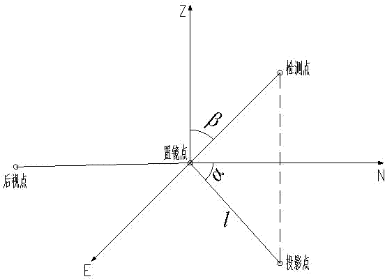
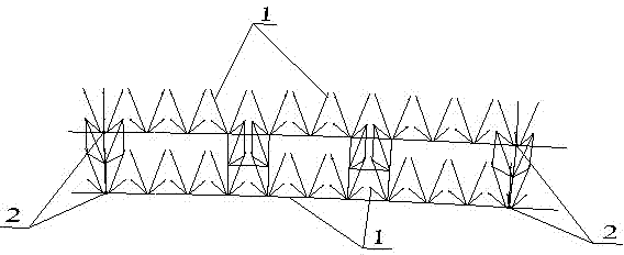
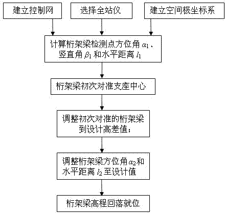
[0035] Such as Figure 1-3 As shown, a truss girder accurate in-position detection method includes the following steps:

[0036] Step 1. Establish a control network that meets the design and measurement specifications of the truss girder 1;

[0037]a. The establishment of the planar control network: the truss girder 1 control network can be arranged as a triangular network, a corner network, a triangular network, a precision wire network, a GPS network, etc. It is difficult to select points in high mountain areas, and the GPS satellite asterisk is not very good. It is more manpowe...


PUM


Abstract

The invention relates to a precise locating detecting method for a truss girder. The method includes the steps: building a controlling net meeting requirements of truss girder design and measurement standard; selecting a measurement instrument as a total station; building a space polar coordinate system; calculating truss girder detecting point design value: an azimuth alpha 1, a vertical angle beta 1 and a horizontal distance l1; a truss girder detecting point is first aligned to a support center; height difference between the support center and a corresponding top face of a lower chord is measured and adjusted to design height difference value; whether the truss girder is located horizontally and correctly is judged according to deviation between the design value and actual value of azimuth and between the design value and the actual value of the horizontal distance of a setting point of the truss girder detecting point, and the truss girder detecting point is adjusted to a design position; and a jack is adjusted so as to enable the truss girder to fall back to design elevation and be located. The precise locating detecting method for the truss girder is high in detecting efficiency and precision, reliable in result, especially suitable for locating detection of truss girders which are small in bent radius and various in linear structures.

Description

technical field [0001] The invention relates to a bridge detection method, in particular to a truss girder accurate detection method. Background technique [0002] At present, the detection method of truss girder, due to the requirement of precision, generally uses the total station to detect its plane position and the level to detect its elevation respectively. The specific detection methods include: Cartesian coordinate method, distance intersection method, angle intersection method , plane polar coordinate method, etc. When the truss bridge is in a mountainous area, if a level is used, the height difference between the known leveling point and the point to be measured must not be too large, but the environment in the mountainous area is complex, and the bridge line structure is diverse, so it is difficult to meet the use conditions of the level; in addition, the Cartesian coordinate method Although the detection equipment used is a total station, the disadvantage is that...

Claims


Application Information

Patent Timeline
IPC IPC(8): G05D3/00G01C5/00
Inventor 李治强彭继安陈幼林杨毅刘延龙王岑申瑞烂巨建基徐仁华杨肃钟唐勇李丽董凤杰周川岭樊建国冉军
Owner CHINA RAILWAY 23RD CONSTR BUREAU LTD
Learn More