
Direct-current-side voltage control method of cascaded STATCOM (static var compensator) based on chopping-control voltage sharing and control circuit

A technology of DC side voltage and control method, applied in flexible AC transmission system, reactive power adjustment/elimination/compensation, etc., can solve the problems of small adjustment range, low harmonic frequency, limited range, etc., to improve reliability, Capacitor voltage is stable and balanced, and the effect of cost reduction

Inactive Publication Date: 2012-11-14
XI AN JIAOTONG UNIV
View PDF2 Cites 18 Cited by
  • Summary
  • Abstract
  • Description
  • Claims
  • Application Information

AI Technical Summary

Problems solved by technology

Changing the pulse width or phase angle makes the CMI output voltage waveform asymmetrical and introduces more harmonics; when the number of power modules is large and the inconsistency difference is greater, the harmonic frequency introduced by this method will be lower, The adjustment range of the phase angle is also smaller, so the applicable range of this method is very limited

Method used

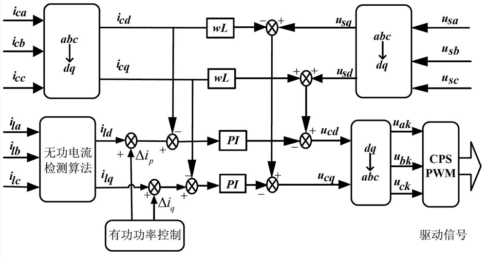
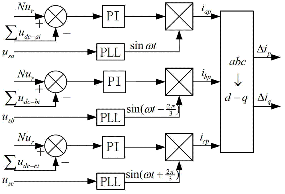

Image

  • Direct-current-side voltage control method of cascaded STATCOM (static var compensator) based on chopping-control voltage sharing and control circuit
  • Direct-current-side voltage control method of cascaded STATCOM (static var compensator) based on chopping-control voltage sharing and control circuit
  • Direct-current-side voltage control method of cascaded STATCOM (static var compensator) based on chopping-control voltage sharing and control circuit

Examples


Embodiment Construction

[0044] The present invention will be described in detail below in conjunction with the accompanying drawings.

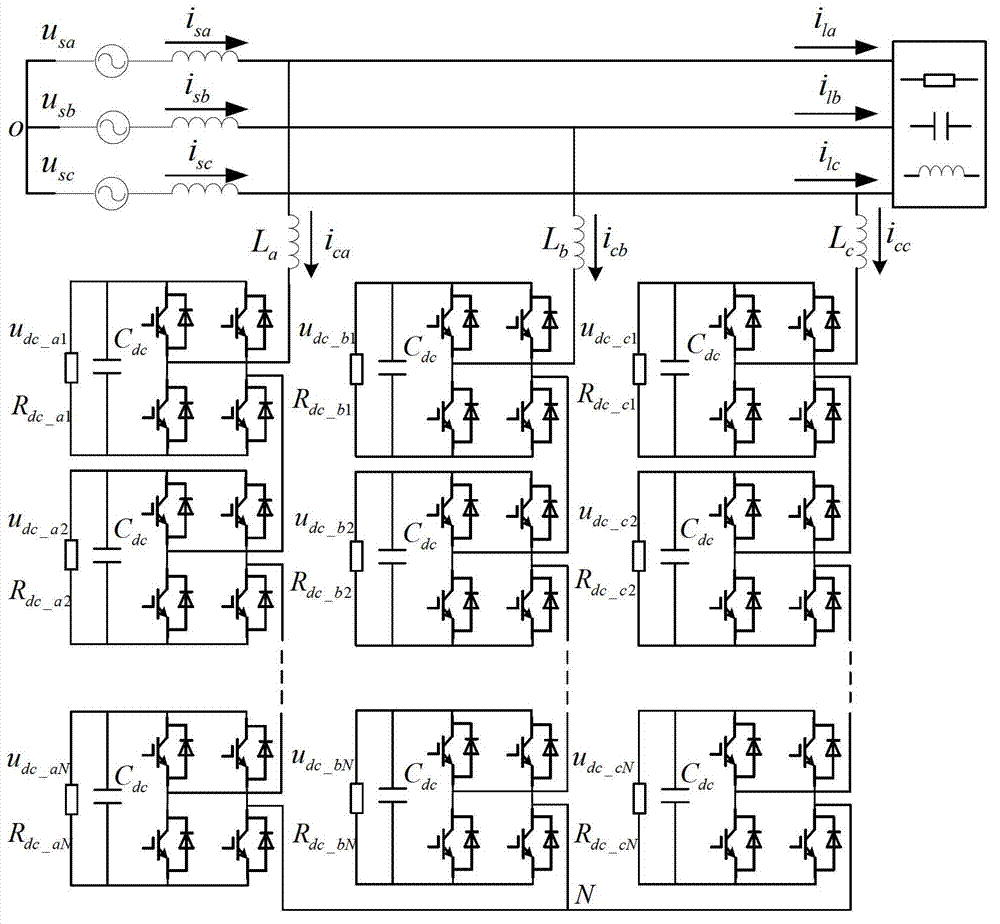
[0045] The structure of chained STATCOM is as follows figure 1 As shown, it is composed of grid, reactive load, connected inductor, and cascaded multilevel inverter (Cascaded Multilevel Inverter, CMI). The CMI consists of N power modules connected in series. The present invention is illustrated with a star connection structure, and the control method of a delta connection can be deduced by analogy. The CMI of each phase is connected in parallel to the common connection point (Point of Common Coupling, PCC) of the system by connecting the inductor in series. The power module that constitutes CMI is a complete single-phase inverter, including independent power switch tube, DC side power supply, drive circuit, detection circuit, protection and control circuit, etc. figure 1 The power module shown is a single-phase 2H bridge inverter, which is the most commonly used p...


PUM


Abstract

The invention relates to a direct-current-side voltage control method of a cascaded STATCOM based on chopping-control voltage sharing, and a control circuit. The control circuit comprises a three-phase star-connection inverter, a two-way switch device and a controller, and is characterized in that the three-phase star-connection inverter is connected with a three-phase power grid through three inlet inductors; each phase of the inverter consists of n pieces of 2H bridge inverter circuit modules serially connected with each other and having an independent direct-current-side capacitor; the direct-current-side capacitors of the n pieces of inverter circuit modules are connected in parallel; and a two-way chopping-control switch is respectively connected with both ends of the i direct-current-side capacitor and with both ends of the (i-1) direct-current-side capacitor in parallel connection with the i direct-current-side capacitor, wherein i is a natural number from 2 to n. The direct-current-side voltage control method provided by the invention can effectively and reliably solve the key problem limiting the use of the STATCOM with the structure in a high-voltage large-capacity occasion, and can simplify the control program and the design of a regulator, greatly improve the system reliability, and remarkably lower the voltage-sharing control cost, thereby realizing the reliable application of the cascaded STATCOM in high-voltage large-capacitor power equipment.

Description

Technical field: [0001] The invention belongs to the field of electric energy quality control research, in particular to a DC side voltage control method and a control circuit of a medium-high voltage chained STATCOM. Background technique: [0002] The chained STATCOM has significant advantages such as large number of levels, less harmonic content, small passive components, and good expansion performance; it plays a role in compensating reactive power in the power transmission and distribution system, improving the stability of the system voltage and improving the operating performance of the system It is an effective means to solve the power quality problem in the field of medium and high voltage and large capacity, and it is one of the core technologies of the Flexible AC Transmission System (FACTS). [0003] The excellent performance of the chained STATCOM and the existing system control strategy are based on the perfect consistency of each power module, that is, each pow...

Claims


Application Information

Patent Timeline
IPC IPC(8): H02J3/18
CPCY02E40/16Y02E40/10
Inventor 卓放熊连松
Owner XI AN JIAOTONG UNIV
Learn More