

Heat-dissipating tape and method for manufacturing same
A production method and tape technology, applied in chemical instruments and methods, adhesives, and other household appliances, can solve problems such as shortened service life and defective products, and achieve effective heat dissipation, excellent thermal conductivity, and excellent heat dissipation effects.
Active Publication Date: 2012-11-14
YOULCHON CHEM
View PDF4 Cites 24 Cited by
- Summary
- Abstract
- Description
- Claims
- Application Information
AI Technical Summary
Problems solved by technology
Therefore, if the emitted heat cannot be removed, it will easily lead to shortened service life or defective products
Method used
View moreImage
Smart ImageViewing Examples

Examples
Embodiment 1
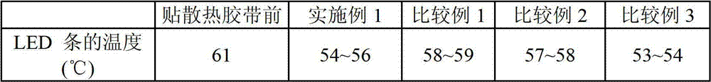
[0054] The heat dissipation tape in Example 1 showed a heat dissipation effect of reducing the temperature of the LED strip by 5-7°C. In Comparative Example 1, the temperature of the LED strip was reduced by 2-3°C, and in Comparative Example 2 by 3-4°C. At this time, since the thermal conductivity of the PET substrate and the adhesive is low, the heat dissipation effect will be reduced. Although comparative example 3 has the effect of lowering the temperature by 7~8°C, at this time, because the coating is easy to fall off or the adhesion is not good, the heat dissipation effect cannot be sustained.
Login to View More PUM
 Abstract
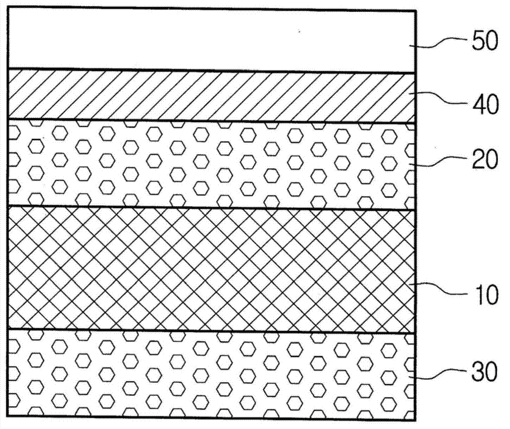
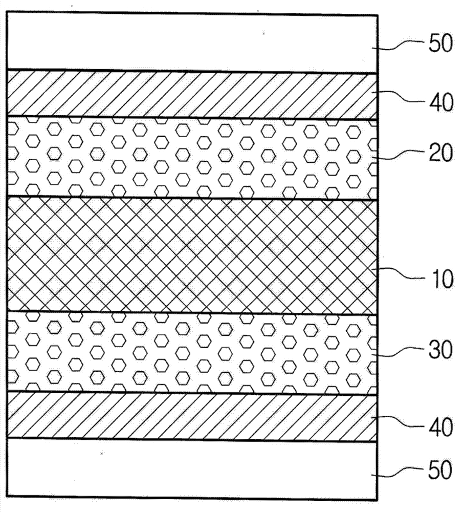
The present invention relates to a heat-dissipating tape to be used in a variety of electronic products so as to dissipate heat from said electronic products, and to a method for manufacturing the heat-dissipating tape. The heat-dissipating tape of the present invention comprises: a metal mesh base; and a heat-dissipating paint layer, wherein the heat-dissipating paint layer is formed on one side or either side of the metal mesh base. In addition, the heat-dissipating tape of the present invention comprises: a metal mesh base; a heat-dissipating paint layer; and an adhesive layer, wherein the heat dissipating paint layer is formed on one side or either side of the metal mesh base, and the adhesive layer is made of thermally conductive adhesives.; The heat-dissipating tape of the present invention is thin, dissipates heat in a vertical direction with respect to a heat-generating source to thereby achieve improved heat-dissipating effects, and has superior adhesion.
Description
technical field [0001] The present invention relates to a heat dissipation tape and a manufacturing method thereof, and more specifically relates to a heat dissipation tape for dissipating heat from parts or devices of electronic products, parts or devices of automobiles and a manufacturing method thereof. Background technique [0002] Recently, electrical, electronic or automotive components or devices such as televisions, video players, computers, medical equipment, office equipment, communication equipment, etc. have become more and more complex. Although electronic components and the like have become more and more complex, the image of the components themselves has continued to be miniaturized due to the gradual reduction in area and the increase in the number of electronic components to be assembled due to miniaturization and higher performance. Therefore, in order to prevent malfunctions and defects caused by the increase of heat generated by each electronic component,...
Claims
Login to View More Application Information
Patent Timeline
 IPC IPC(8): C09J7/00C09J9/02B32B15/02H05K7/20C09J7/29
CPCC08K3/04B32B2457/20C09J7/0296B32B7/12C09D5/32B32B15/02C09J2483/00H05K7/20481B32B15/20C09J2205/106C09J2203/318C09J2400/163H05K7/20963C09J2433/00C09J2475/00C09D5/18B32B5/02B32B7/06B32B15/08B32B15/18B32B27/10B32B27/12B32B27/18B32B27/308B32B27/36B32B29/02B32B2307/30B32B2307/302B32B2307/732B32B2457/00C09J7/29C09J2301/41
Inventor 郑在哲姜汉俊李星昊金志姬
Owner YOULCHON CHEM