Location method of curved-edge blank formed by hot stamping

A technology of hot stamping forming and positioning method, which is applied in the field of sheet metal stamping and forming, can solve the problem of inability to precisely control the placement position of the sheet metal, and achieve the effects of reducing trimming allowance, accurate positioning, and reducing wrinkling and cracking.

Inactive Publication Date: 2015-04-08
武汉钢铁有限公司 +1
View PDF5 Cites 0 Cited by
  • Summary
  • Abstract
  • Description
  • Claims
  • Application Information

AI Technical Summary

Problems solved by technology

However, the precise sheet obtained by the finite element inverse algorithm has high requirements on the initial placement position of the sheet before stamping. It is transported by mechanical devices, and the placement position of the sheet cannot be precisely controlled without a positioning device.

Method used


Image

  • Location method of curved-edge blank formed by hot stamping
  • Location method of curved-edge blank formed by hot stamping
  • Location method of curved-edge blank formed by hot stamping

Examples


Embodiment 1

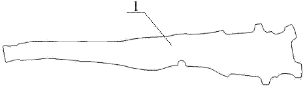
[0018] 1) According to the 3D surface digital model of the final design of the finished part, use the finite element inverse algorithm to calculate the precise blank 1 obtained after the part is expanded through the sheet metal before forming, such as figure 1 shown;

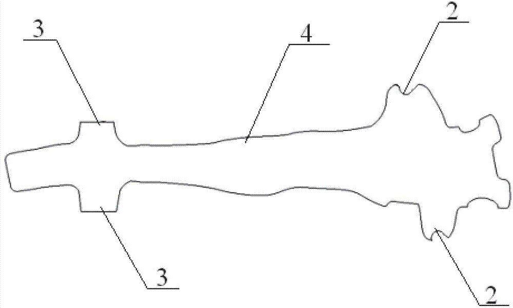
[0019] 2) Analyze the characteristic shape of the part, retain the positioning surplus material when the sheet is cut, form positioning ears 2 that limit the plane movement of the precise blank 1 on both sides of one end of the precise blank 1, and form a restrictive precision on both sides of the other end of the precise blank 1 The positioning surplus block 3 that blank 1 moves along the width direction obtains curved edge sheet 4, such as figure 2 As shown, the outside of the positioning ear 2 is a curved edge, and the outside of the positioning surplus block 3 is a straight edge; The shape of the bit block 5 is a cylinder with an inclined plane at the top;

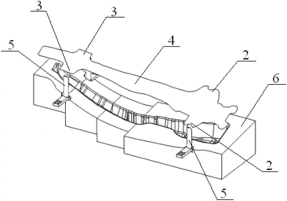
[0020] 3) if image 3 As shown, the curved edg...

Embodiment 2

[0022] 1) According to the 3D surface digital model of the final design of the finished part, use the finite element inverse algorithm to calculate the precise blank 1 obtained after the part is expanded through the sheet metal before forming, such as figure 1 shown;

[0023] 2) Analyze the characteristic shape of the part, keep the positioning surplus material when the sheet is cut, form the positioning ears 2 that limit the plane movement of the precise blank 1 on both sides of the middle of the precise blank 1, and form the restrictive precise blank on both sides of the two ends of the precise blank 1 1. Move the positioning block 3 along the width direction to obtain the curved edge sheet 4. The outside of the positioning ear 2 is a curved edge, and the outside of the positioning block 3 is a straight edge; 3 Install the sheet material limit block 5 at the corresponding position, and the shape of the sheet material limit block 5 is a cuboid with a slope at the top;

[002...


PUM


Abstract

The invention discloses a location method of curved-edge blank formed by hot stamping. The method comprises steps as follows: 1) calculating an accurate blank obtained by unfolding a part through a plate before formation according to a final design of a finished part; 2) retaining a locating surplus material while cutting the plate, forming a locating lug for limiting plane motion of the accurate blank and a locating surplus block for limiting motion of the accurate blank along a width direction, thus obtaining curved-edge plate, and furthermore, mounting a plate limiting block on a mould, wherein an inclined surface is formed at a top end of the plate limiting block; and 3) transporting the curved-edge plate onto the mould, sliding the curved-edge plate into a preset position in the mould through limitation action of the locating lug and the locating surplus block on the curved-edge plate as well as the inclined surface on the plate limiting block, thereby accurately locating the curved-edge plate at an initial stamping position. According to the locating method of the curved-edge blank formed by hot stamping, disclosed by the invention, the relatively narrow curved-edge plate can be accurately disposed on the mould because of use of the plate limiting block, therefore, the locating method has the advantages of accurate location of plates, high repeatability precision, reduced deburring allowance and material saving, and is suitable for volume production.

Description

technical field [0001] The invention relates to sheet material stamping forming, in particular to a positioning method for hot stamping curved edge blanks. Background technique [0002] Automobile energy conservation and emission reduction and improvement of ride safety are the most urgent problems to be solved in the automobile industry, and lightweight is one of the most effective means and ways to achieve energy conservation and emission reduction. For every reduction of 100 kg in vehicle curb weight, fuel consumption per 100 kilometers can be reduced by 0.3-0.6 liters, and emissions can be reduced by 4%-6%. After hot stamping of high-strength steel, the structure of the material will change from the austenite structure in the heated state, and the forming and quenching of the parts will be completed synchronously by using a low-temperature mold. Therefore, it is possible to reduce the thickness of the material and realize the weight reduction of the vehicle body. [00...

Claims


Application Information

Patent Timeline
Patent Type & Authority Patents(China)
IPC IPC(8): B21D43/00
Inventor 葛锐张宜生龙安王超薛欢黄志高陈寅吴青松
Owner 武汉钢铁有限公司
Why Eureka
Try Eureka