Rotary shaft body and rotary knife including the rotary shaft body
A technology of rotating shafts and rotating knives, which is applied in metal processing and other directions, can solve the problems of increased cost of the knife support body, and achieve the effect of improving strength, reducing labor and time
- Summary
- Abstract
- Description
- Claims
- Application Information
AI Technical Summary
Problems solved by technology
Method used
Image

Examples
Embodiment 1
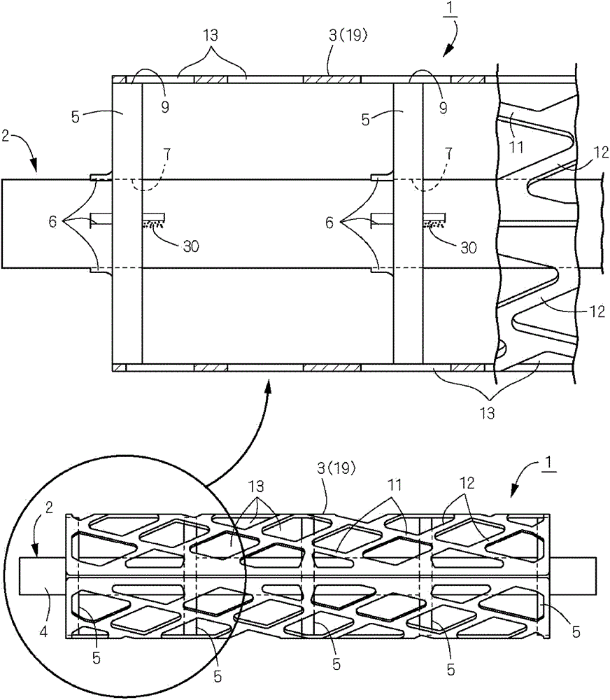
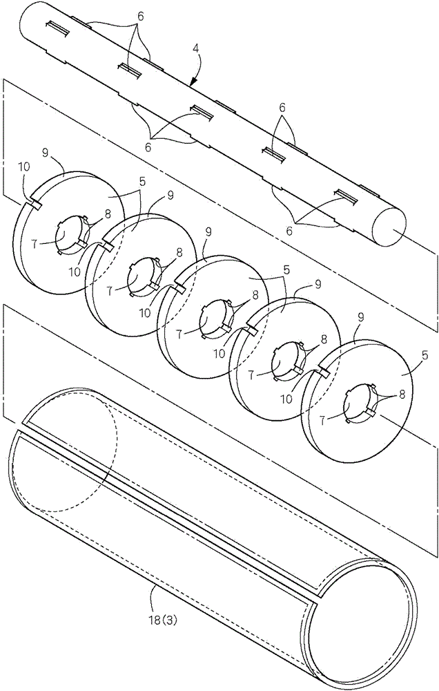
[0069] Figure 1 to Figure 9 An example of a rotary knife including the rotary shaft body of the present invention is shown. exist figure 1 and figure 2 Among them, the rotary knife 1 is composed of a rotary shaft body 2 and a cutting knife 3 fixed on the rotary shaft body 2 . The rotating shaft body 2 is composed of a shaft main body 4 and five discs 5 press-fitted and fixed on the shaft main body 4 . The shaft main body 4 is made of martensitic round shaft-shaped stainless steel material. The disk 5 is formed in a disk shape by pressing (punching) a plate made of austenitic stainless steel.
[0070] In order to press-fit and fix (rivet) the disks 5 to the shaft main body 4 , a plurality of press-fit protrusions 6 are formed on the peripheral surface of the shaft main body 4 corresponding to the fixed positions of the respective disks 5 . The press-fit protrusions 6 are formed by corroding the peripheral surface of the shaft body 4, and in this embodiment, rib-shaped pr...
Embodiment 2
[0099] Figure 10 and Figure 11 Another embodiment of the rotating shaft body 2 is shown. Here, similar to the previously described embodiment, the rib-shaped press-fit protrusions 26 are intermittently formed at regular intervals along the axial direction of the shaft body 4 , but the form of pressing the disk 5 to the shaft body 4 is different. Such as Figure 10 As shown in (a), insert the disc 5 with the shaft main body 4 and temporarily assemble it, as Figure 10 As shown in (b), the press-fitting protrusion 6 to be press-fitted is inserted into the disk 5, and the press-fitting posture is maintained in a state where the relief groove 8 and the press-fitting protrusion 6 are fitted. In this state, if Figure 10 (b) As shown by the arrow, the disc 5 is rotated and operated to press the filling hole 7 and the protrusion 6 for press-fitting into each other, so that the disc 5 and the shaft main body 4 are integrated. At this time, each disk 5 can be fixedly held by the...
Embodiment 3
[0103] Figure 13 ~ Figure 17 Still another embodiment of the rotating shaft body 2 is shown. Wherein, same as the first embodiment, the rotary knife 1 is formed by the rotary shaft body 2 and the cutting knife 3 fixed on the rotary shaft body 2 .
[0104] The rotating shaft body 2 is composed of a shaft main body 4 and five discs 5 press-fitted and fixed on the shaft main body 4 . Only the charging hole 7 through which the shaft main body 4 is inserted is formed in the center of the disk-shaped disk 5, and the relief groove 8 of the previous embodiment is omitted. The disk 5 is formed in a disk shape by punching an austenitic stainless steel material (stainless steel plate material). Alternatively, etching may be performed on a stainless steel plate material to form a disc shape. The shaft main body 4 is made of martensitic round shaft-shaped stainless steel material.
[0105] The disk 5 is press-fitted and fixed on the shaft main body 4 in the same manner as in the previ...
PUM
 Abstract
Description
Claims
Application Information