
On-vehicle electronic control apparatus

A vehicle-mounted electronic control and vehicle-mounted battery technology, applied in the direction of circuit devices, battery circuit devices, collectors, etc., can solve the problems of increased cost and power consumption of regulated power supply circuits, and achieve low consumption, stable power supply, and low power consumption. cost effect

Active Publication Date: 2012-11-21
MITSUBISHI ELECTRIC CORP
View PDF6 Cites 11 Cited by
  • Summary
  • Abstract
  • Description
  • Claims
  • Application Information

AI Technical Summary

Problems solved by technology

In addition, if the output voltage Vcp is intentionally increased compared with the minimum holding voltage of the backup memory, this problem can be solved, but in this case, there is a disadvantage that the work of the stabilized power supply circuit that generates the output voltage Vcp Larger power consumption will lead to larger size and higher cost

Method used


Image

  • On-vehicle electronic control apparatus
  • On-vehicle electronic control apparatus
  • On-vehicle electronic control apparatus

Examples


Embodiment approach 1

[0063] (1) Structure description

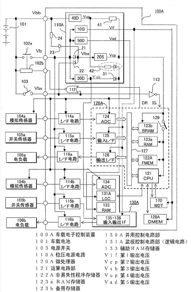
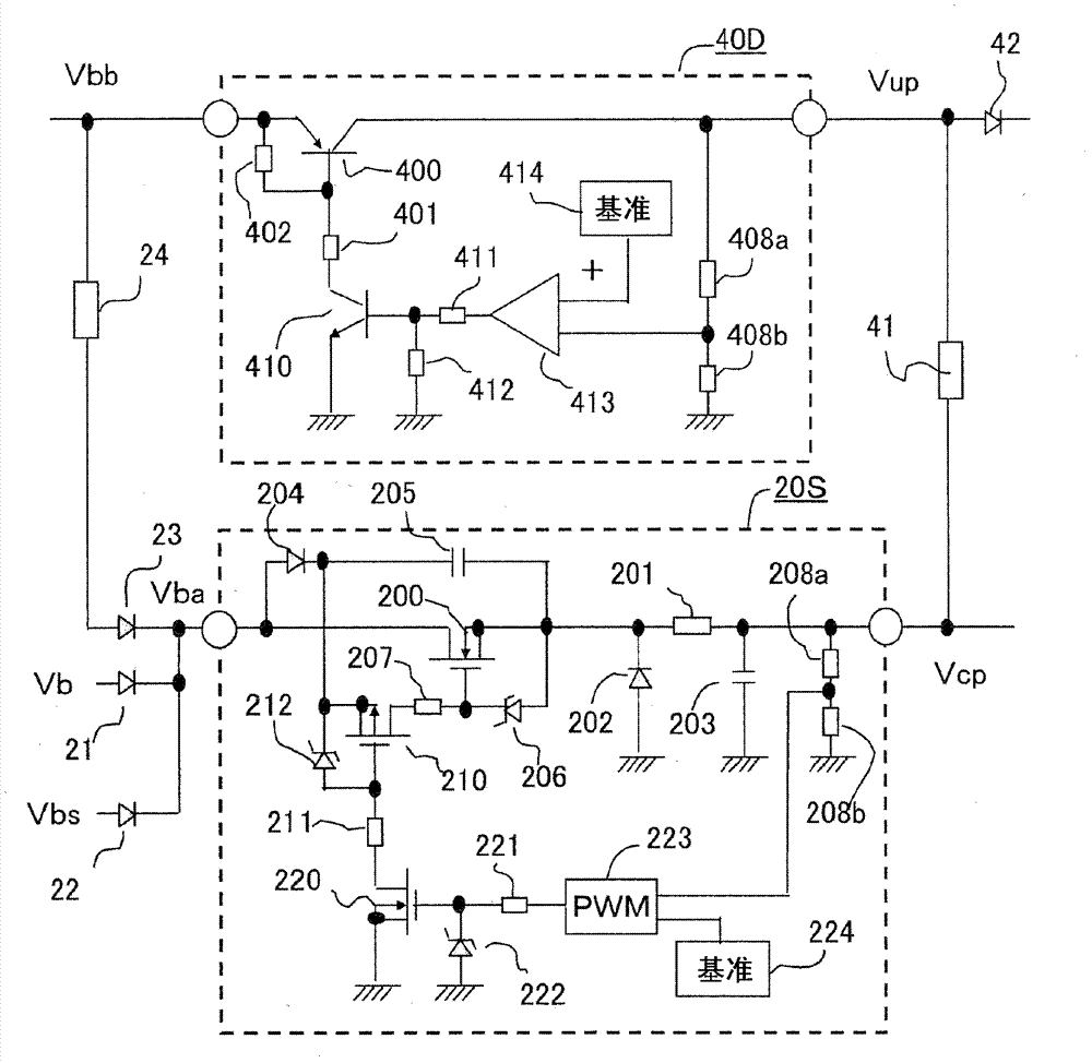
[0064] figure 1 It is a block diagram of the overall circuit of the in-vehicle electronic control device according to Embodiment 1 of the present invention. exist figure 1 Among them, the main power supply voltage Vb is applied from the on-vehicle battery 101 to the on-vehicle electronic control device 100A through the output contact 102a of the power relay, and even when the output contact 102a is open, the holding power supply voltage Vbb can be directly applied from the on-vehicle battery 101. However, since the direct power supply line uses a thin wire for relatively small power, there is a problem that the line voltage drops even if a large current flows temporarily. The excitation coil 102b of the power relay is controlled by the on-vehicle electronic control unit 100A so that it is excited when the power switch 103 is turned on, and de-energized after a predetermined time delay when the power switch 103 is turned off. The first anal...

Embodiment approach 2

[0116] (1) Structure description

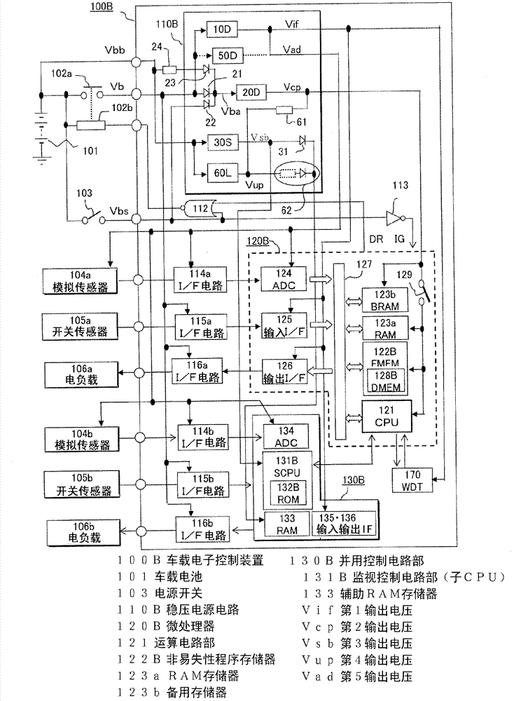
[0117] For the vehicle-mounted electronic control device according to Embodiment 2 of the present invention, refer to the overall circuit diagram that is image 3 , and a detailed circuit diagram of a part of the regulated power supply circuit is Figure 4 , with figure 1 , figure 2 The differences will be explained centering on. Furthermore, in the figure, with figure 1 , figure 2 The same reference numerals represent the same or corresponding parts.

[0118] exist image 3 In, for the vehicle electronic control device 100B with figure 1 Same as the vehicle battery 101, the output contact 102a of the power relay, the exciting coil 102b, the power switch 103, the first analog sensor 104a, the second analog sensor 104b, the first switch sensor 105a, the second switch sensor 105b, the first vehicle sensor The electric load group 106a is connected to the second on-vehicle electric load group 106b, and the main power supply voltage Vb, ...


PUM


Abstract

A fourth constant-voltage power circuit (40D) directly powered from an on-vehicle battery (101) is connected, in parallel through a serial resistor (41), to a second constant-voltage power circuit (20S) powered from the on-vehicle battery through an output contact (102a) of a power relay, and is connected to a drive power terminal of a microprocessor. When the output contact is closed, the microprocessor (120A) operates with an output voltage of the second constant-voltage power circuit, and an output current of the fourth constant-voltage power circuit (40d) is limited to less than or equal to a predetermined value by the serial resistor (41). During the operation stop at which a power switch (103) is open, a micro standby current is supplied from the fourth constant-voltage power circuit (40D) to the microprocessor.

Description

technical field [0001] The present invention relates to vehicular electronic control devices, and more particularly to vehicular electronic control devices including a power supply circuit suitable for use with a low-power consumption type microprocessor with a built-in backup disconnect switch to provide CPU drive from a common power supply terminal. current and backup current for RAM memory. Background technique [0002] A vehicle-mounted electronic control device having a plurality of regulated power supply circuits is known. In the plurality of regulated power supply circuits, compared with the power supply voltage Vcc (for example, DC5V) for the interface circuit, the cost of the nonvolatile program memory, volatile The drive power supply voltage Vdd (for example, DC3.3V) of the arithmetic circuit unit that works in conjunction with the volatile RAM memory supplies the RAM memory with a battery-backed hold voltage Vup to enable the microprocessor to operate at high spee...

Claims


Application Information

Patent Timeline
Patent Type & Authority Applications(China)
IPC IPC(8): B60R16/03H02J7/00
CPCG06F1/189B60R16/03G06F1/3293G06F1/30
Inventor 西田充孝木村友博藤田昌英图子雄二
Owner MITSUBISHI ELECTRIC CORP
Learn More