System and process for pulverized coal injection of blast furnace

A pulverized coal injection and blast furnace technology, applied in the field of metallurgy, can solve problems such as large fluctuations in injection volume, unbalanced contact, and Louis blockage of injection pipes, so as to reduce the consumption of conveying gas, reduce the probability of powder blocking, and effectively Conducive to the effect of stable transportation

Active Publication Date: 2012-11-21
WISDRI ENG & RES INC LTD
View PDF3 Cites 6 Cited by
  • Summary
  • Abstract
  • Description
  • Claims
  • Application Information

AI Technical Summary

Problems solved by technology

[0004] 1. Due to the structural design of the gas supply device itself, local disturbances will occur at the inlet point of the coal injection pipeline, and the gas supply device and the pipeline are easily worn locally. In order to prolong the service time of some blast furnace coal injection devices, each injection tank Install an air supply device on the pipeline between the injection main pipe, but this will increase the cost and complicate the system;
[0005] 2. The gas replenisher is installed at the horizontal injection main pipe. Since the pulverized coal in the dense phase conveying pipeline will form a "dense flow" in the lower section of the pipeline under the action of gravity, the contact between the supplementary gas and the pulverized coal is uneven. , it is easy to form a larger pulsation, so that the injection volume fluctuates greatly;
[0006] 3. Since the air replenisher is set at the injection main pipe after the confluence of multiple injection branch pipes, it is easy to cause the probability of powder blockage at the connection between the injection branch pipe and the injection main pipe to increase
[0007] At the same time, the existing tank-merging coal injection system still has problems such as the injection volume cannot be adjusted accurately, the injection is uneven, and the injection pipeline is easily blocked.

Method used


Image

  • System and process for pulverized coal injection of blast furnace

Examples


Embodiment Construction

[0034] The present invention will be further described below in conjunction with the accompanying drawings and examples, but of course the following examples should not be construed as limiting the present invention.

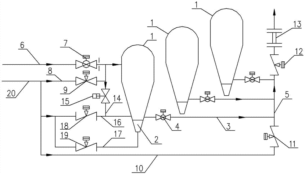
[0035] Such as figure 1 As shown, it is the blast furnace pulverized coal injection system provided by the embodiment of the present invention, which includes three injection tanks 1 arranged side by side, a fluidization tank 2 arranged at the bottom of each injection tank 1, and each injection tank 1 The blowing branch pipe 3 connected to the outlet of the blowing tank 1, the coal injection valve 4 arranged on each blowing branch pipe 3, the blowing main pipe 5 connected to the outlets of the three blowing branch pipes 3, and the 1 connected pressure-charging pipeline 6, a pressure-filling valve 7 arranged on the pressure-charging pipeline 6, a pressure-stabilizing pipeline 8 connected to each blowing tank 1, and a pressure-stabilizing pipeline 8 arranged on th...


PUM


Abstract

The invention provides a system and a process for pulverized coal injection of a blast furnace. The system comprises a plurality of parallel injection tanks, fluidization tanks, injection branch pipes, coal injection valves, an injection main pipe, a charging pipeline, a charging valve, a pressure stabilizing pipeline, a pressure stabilizing valve, a gas supplementing pipeline, a gas supplementing regulating valve, a pulverized coal flow regulating valve and a pulverized coal flow meter, wherein one fluidization tank is arranged at the bottom of each injection tank, one injection branch pipe is connected with an outlet of each injection tank, one coal injection valve is arranged on each injection branch pipe, the charging pipeline and the pressure stabilizing pipeline are connected with each injection tank, the injection main pipe is vertically arranged, the pulverized coal flow regulating valve and the pulverized coal flow meter are arranged on the injection main pipe from bottom to top, the gas supplementing pipeline is connected to the bottom end of the injection main pipe, and the gas supplementing regulating valve is arranged on the injection main pipe and below the joints of the injection branch pipes and the injection main pipe. By the aid of the system and the process, pulverized coal can be uniformly and stably injected, injection quantity is accurately controlled, pulverized coal dense phase transportation technology can be realized, gas consumption is low, and pipeline abrasion is less.

Description

technical field [0001] The invention belongs to the technical field of metallurgy, and in particular relates to a blast furnace pulverized coal injection system and process. Background technique [0002] In the process of pulverized coal injection in the blast furnace, uniform and stable injection and precise control of the injection volume are one of the important conditions to improve the reliability of the coal injection system and ensure the smooth flow of the blast furnace charge. The core lies in the uniform stability and adjustable sex, economy. Uniform stability means: the injection process is continuous, and the fluctuation of the injection amount is small; adjustability means: according to the operation needs of the blast furnace, the injection amount can be adjusted in time to meet the requirements of the heat system of the blast furnace hearth for the amount of pulverized coal; economy means: in Reducing production costs under the premise of safe and reliable pr...

Claims


Application Information

Patent Timeline
Patent Type & Authority Applications(China)
IPC IPC(8): C21B7/00C21B5/00
Inventor 汤楚雄闫朝付周少丰周强司敬芝李啸磊
Owner WISDRI ENG & RES INC LTD
Why Eureka
Try Eureka