Floating structure connected by tension connector with adjustable length

A technology for adjusting the length of floating structures, which is applied to floating buildings, pontoon bridges, bridge parts, etc., can solve the problems of uneven joint gap, uneven force on joints, large bending moments at rigid joints, etc., and achieve manufacturing accuracy less demanding effect

Inactive Publication Date: 2012-11-21
吴广怀
View PDF0 Cites 13 Cited by
  • Summary
  • Abstract
  • Description
  • Claims
  • Application Information

AI Technical Summary

Problems solved by technology

In order to quickly assemble the floating body unit, the machining accuracy of the floating body unit is required to be high, and the manufacturing of the floating body unit needs to be completed on the tooling tire frame, so that the size of the floating body unit is limited to a small range, and it is difficult to provide a large floating body unit
In addition, due to the wave load, a large bending moment will be generated at the rigid joint, a large hinge force will be generated at the hinged joint, and the stress concentration at the joint
Due to the uneven gap between the joints, the stress on the joints on the same section is uneven, and the effect of increasing the bearing capacity by increasing the number of joints is also limited, so the ability of this type of floating structure to resist wind and waves is low
Among the above-mentioned joints, except for the longitudinal connecting plate and the hinge, the rest of the joints are welded to the floating body unit, which cannot be replaced after damage. Controlled by the fatigue life of the joints, this type of floating structure has a short service life in waves

Method used


Image

  • Floating structure connected by tension connector with adjustable length
  • Floating structure connected by tension connector with adjustable length

Examples


Embodiment Construction

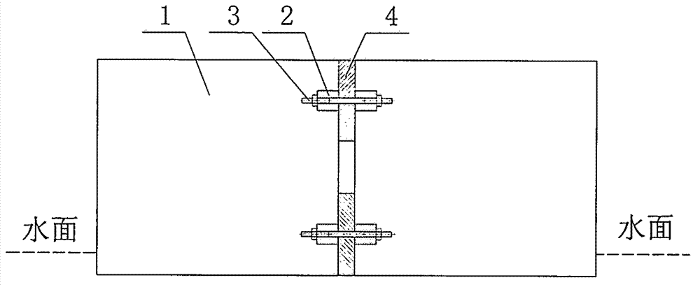
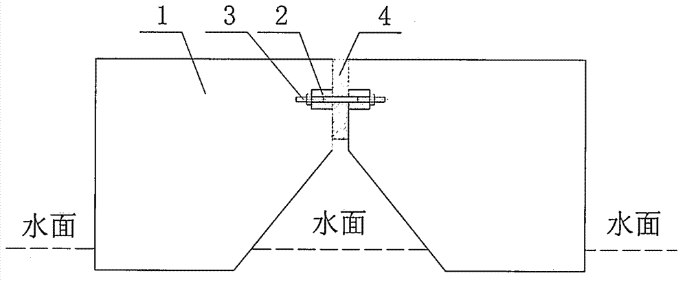
[0010] figure 1 Among them, the connecting surface of the floating body unit (1) is provided with upper and lower two-layer connector mounts (2), after the adjustable-length tension connector (3) is inserted into the connector mount (2), tighten the connector nut , and achieve the same degree of tightness of the tension connectors (3) on the same connecting surface. Each layer can be installed with multiple tension connectors according to the force requirements. Since the elastic buffer material (4) is installed between the corresponding floating body units (1), when the nut of the connector is tightened, the tension connector (3) is subjected to a certain initial tension, and the elastic buffer material (4) is subjected to a certain initial pressure effect, so that there will be no impact effect between the connection between the traditional pontoon bridge and the pontoon. figure 1 Only the tension connectors installed horizontally are shown in the figure. Since the tension...


PUM


Abstract

The invention discloses a floating structure connected by a tension connector with adjustable length. Floating body cells are connected by the tension connector with adjustable length, and elastic buffer material is installed among the floating body cells; a pull force is borne by the tension connector; a pressure is borne by the elastic buffer material and the floating body cells; and a shear force is borne by an inclined tension connector which forms an angle with a connection surface. Both a rigid joint and a hinge joint of the combined floating structure have certain elasticity and can bear a large wave load. Because the length of the tension connector can be adjusted and the requirement on the manufacturing precision of the floating body cells is low, bigger floating body cells can be used so that a bigger floating structure can be combined. Because of being not welded together with the floating body cells, the tension connector can be changed so that the service life of the floating structure is not limited by the fatigue life of the connector.

Description

technical field [0001] The invention relates to an assembled floating structure on water, which can be used as a floating bridge, a floating stack, a floating wharf and a floating operation platform. Background technique [0002] Steel thin-walled pontoon bridge and pontoon equipment can be assembled into floating structures such as pontoon bridges, floating stacks, pontoon docks, and floating work platforms on water. The shear pin and the C and D hooks (or L hooks) etc. of the bottom form a rigid connection, and can also be hinged by the hinge on the top. For floating structures assembled by these connection methods, due to the gaps between the joints, the impact between the units is obvious under the action of waves, and the joints will be worn, thereby increasing the gap between the joints and producing a stronger rushing effect. The service life of the quasi-assembled floating structures in waves is relatively short. In order to assemble quickly, the processing accurac...

Claims


Application Information

Patent Timeline
Patent Type & Authority Applications(China)
IPC IPC(8): E01D15/14E01D19/00E01D19/06E02B3/04E02B3/16B63B35/44
Inventor 吴广怀陈徐均陈云鹤于群力王恒
Owner 吴广怀
Why Eureka
Try Eureka