
Three-phase asymmetric power frequency parameter actual measuring method of high-voltage transmission line

A technology for high-voltage transmission lines and power frequency parameters, which is applied to measuring devices, measuring electrical variables, and measuring resistance/reactance/impedance, etc., which can solve the difficulty of ensuring accurate measurement of power frequency parameters of high-voltage transmission lines, and the difficulty of solving high interference induced voltages, etc. problems, to achieve the effect of eliminating strong interference induced voltage and improving accuracy

Inactive Publication Date: 2012-11-21
ELECTRIC POWER RES INST OF GUANGDONG POWER GRID +1
View PDF2 Cites 11 Cited by
  • Summary
  • Abstract
  • Description
  • Claims
  • Application Information

AI Technical Summary

Problems solved by technology

[0004] At present, there are many measurement methods for power frequency parameters of high-voltage transmission lines, such as instrument measurement method, computerized line parameter test method and different frequency method, etc. These test methods are difficult to solve high interference induced voltage, and all of them assume three-phase transmission lines Completely symmetrical, making it difficult to guarantee accurate measurement of power frequency parameters of high-voltage transmission lines

Method used


Image

  • Three-phase asymmetric power frequency parameter actual measuring method of high-voltage transmission line
  • Three-phase asymmetric power frequency parameter actual measuring method of high-voltage transmission line
  • Three-phase asymmetric power frequency parameter actual measuring method of high-voltage transmission line

Examples


Embodiment Construction

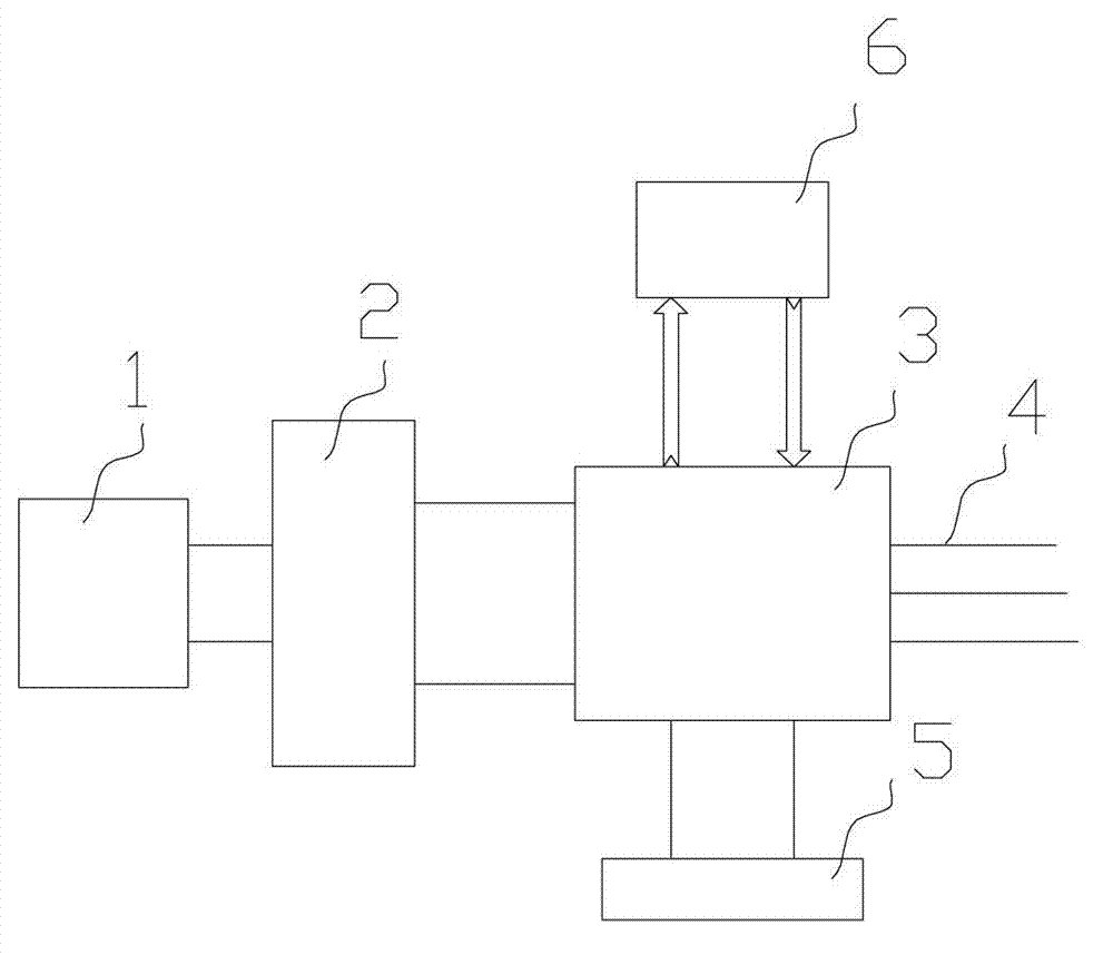
[0029] like figure 1 As shown, the actual measurement device used in the test method of the present invention includes a single-phase power supply 1, a multi-tap transformer 2 and a line parameter tester 3 connected in sequence. The tester 3 is also connected to an external synchronous power supply 5 and a host computer 6 respectively. The output of the tester 3 is connected to the test terminal of the tested line 5 as a test power supply.

[0030] like Image 6 As shown, the composition and connection relationship of the line parameter tester are:

[0031] include:

[0032] Two power input terminals and two capacitor external terminals, in which the power terminal is externally connected to the output end of a multi-tap transformer, and the voltage range is 100V~2000V; the capacitor external terminal is connected to an external capacitor to prevent overvoltage generated during the measurement process;

[0033] The first three-phase line terminals 01, 02, 03 and the second ...


PUM


Abstract

The invention discloses a three-phase asymmetric power frequency parameter actual measuring method of a high-voltage transmission line. The actual measuring method comprises the following steps: 1) the matching end three phases are short-circuited and then grounded; a single phase test power source is implemented between any two phase lines at the measuring end; the other phase is idle; and voltage and current of each phase are measured; 2) the matching end three phases are short-circuited and then grounded; any two phase lines are connected in parallel at the measuring end, and a single phase test power source is implemented between the parallel connected two phase lines and the third phase line, and the voltage and the current of each phase are measured; 3) the matching end three phases are short-circuited and then grounded; a single phase test power source is implemented between any phase of the measuring end and the ground; the other two phases are idle; and the voltage and the current of each phase are measured; 4) a quasi-impedance equation is constructed to obtain the line impedance matrixes; and 5) the line impedance matrixes are subjected to mathematical transform to obtain positive-sequence, negative-sequence, and zero-sequence impedances and coupling impedance between sequences. The measuring method is simple and practical, can eliminate the high-induced voltage interference and influence from three-phase asymmetry to the line parameter measurement, and improves the precision of the line parameter measurement.

Description

technical field [0001] The invention relates to a method for actually measuring three-phase asymmetric power frequency parameters of a high-voltage transmission line, in particular to a method for actually measuring three-phase asymmetric power frequency parameters of a high-voltage power transmission line under strong interference induced voltage. Background technique [0002] Transmission line is an important part of the power system. Its power frequency parameters such as positive sequence parameters, negative sequence parameters, and zero sequence parameters are used for power system power flow calculation, transient stability calculation, relay protection setting calculation and power system operation mode formulation, etc. The necessary parameters to establish the mathematical model of the power system before work, and its accuracy is directly related to the safe and stable operation of the power grid. Due to the influence of geography, environment and other factors, t...

Claims


Application Information

Patent Timeline
IPC IPC(8): G01R27/02G01R27/14
Inventor 尹建华赵艳军陈晓科赵进全盛超杨汾艳孙闻曾杰唐景星王奕胡玉岚张俊峰魏伟李贺龙姜良刚
Owner ELECTRIC POWER RES INST OF GUANGDONG POWER GRID
Learn More