Thermal flowmeter

A thermal flow meter and flow technology, applied in the field of flow meters, can solve problems such as errors and achieve the effect of simple structure

Inactive Publication Date: 2005-10-05
YAMATAKE HONEYWELL CO LTD
View PDF1 Cites 14 Cited by
  • Summary
  • Abstract
  • Description
  • Claims
  • Application Information

AI Technical Summary

Problems solved by technology

Therefore, when the detection temperature of the temperature detection element Rr is affected by the external environment and cannot be accurately measured, and the heating temperature of the heating element Rh deviates from the specified temperature, an error occurs in the flow measurement by the thermal flowmeter.

Method used


Image

  • Thermal flowmeter
  • Thermal flowmeter
  • Thermal flowmeter

Examples


Embodiment Construction

[0035] Hereinafter, a thermal flowmeter according to one embodiment of the present invention will be described with reference to the drawings.

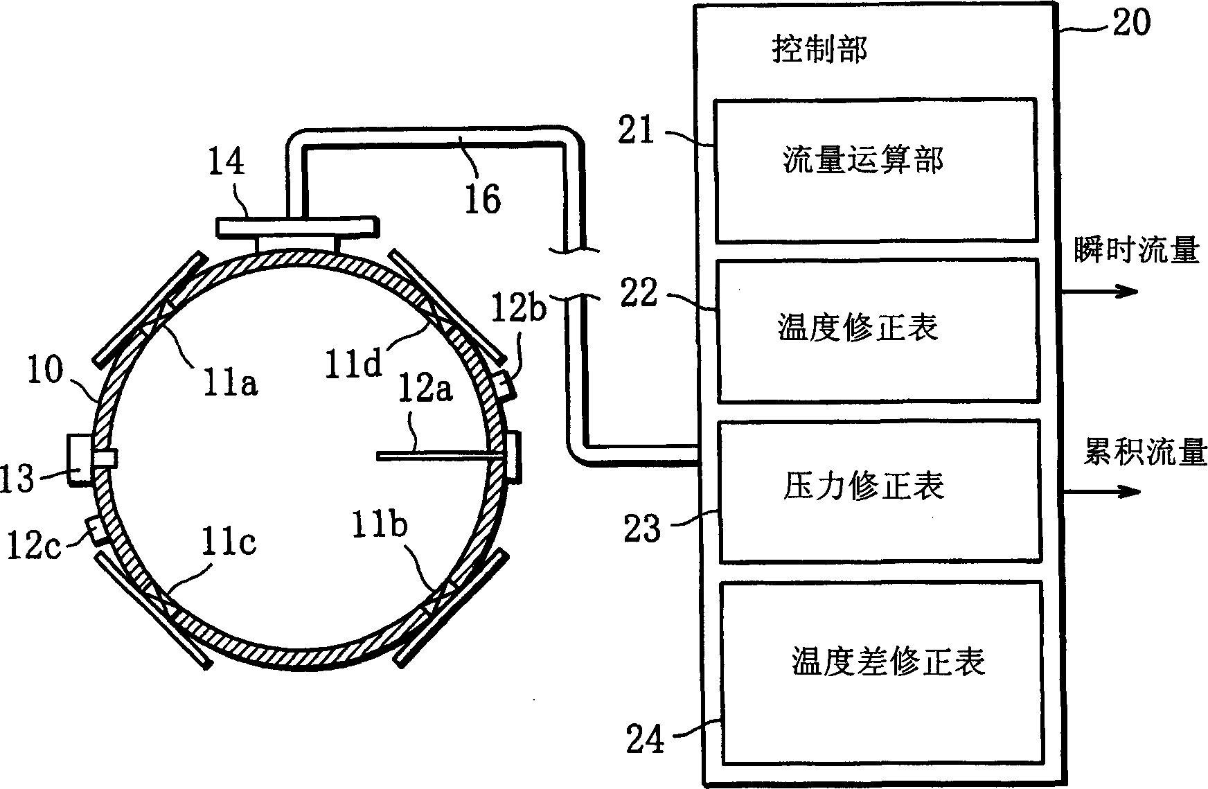
[0036] The thermal flow meter of the present embodiment is configured as a gas meter for measuring the flow rate of gas flowing through a fluid passage formed by pipes. Such as figure 1 As shown, the gas meter includes a plurality of, for example, four thermal flow sensors 11a, 11b that are arranged on the outer wall of the pipeline 10 and respectively send outputs indicating the gas flow rate (more generally, the fluid flow rate) flowing through the pipeline 10. , 11c, 11d; the first temperature sensor 12a for detecting the gas temperature; the second temperature sensor 12b, 12c for detecting the temperature of the pipeline 10; and the pressure sensor 13 for detecting the gas pressure.

[0037] More specifically, each of the thermal flow sensors 11a to 11d basically has a Figure 5 The sensor strip 1 shown has the same structure. ...


PUM


Abstract

A thermal flowmeter comprises a thermal flow sensor having first and second temperature detection elements (Ru, Rd) disposed in the direction of flow of fluid with a heater element (Rh) disposed therebetween, a first temperature sensor (12a) for detecting the temperature of the fluid flowing in a pipe (10), a second temperature sensor (12b, 12c) for detecting the pipe temperature, wherein the flow rate of the fluid is measured from the difference in detection output between the first and second temperature detection elements, while the amount of flow rate correction is found from a temperature difference correction table (24) according to the difference between the pipe temperature and the fluid temperature, the amount of flow rate correction being used to correct the measured fluid flow rate, which correction is capable of eliminating the thermal effect on flow rate measurement from the external environment so as to improve the measurement accuracy.

Description

technical field [0001] The present invention relates to a flow meter, in particular to a thermal flow meter capable of measuring the fluid flow in a pipeline without being affected by the external environment and with high precision. Background technique [0002] The cumulative flowmeter includes a flow sensor for measuring the instantaneous flow rate of the fluid flowing through the fluid channel, and the cumulative flow rate is measured according to the instantaneous flow rate, which is expected to have high measurement accuracy. In particular, since the gas meter accumulates the instantaneous flow rate of gas flowing through the gas pipe over a month, for example, to measure the gas usage amount (cumulative flow rate) used as the basis for calculating the gas usage fee, it requires high measurement. precision. [0003] Therefore, a thermal flow sensor with high measurement accuracy is generally used in an accumulative flow meter such as a recent gas meter. Thermal flow ...

Claims


Application Information

Patent Timeline
Patent Type & Authority Applications(China)
IPC IPC(8): G01F15/02G01F1/684G01F1/696
CPCG01F1/6845G01F1/684G01F1/6965
Inventor 島田勝介村岡学濑户実小牧充典田代健大島英一石谷聡
Owner YAMATAKE HONEYWELL CO LTD
Why Eureka
Try Eureka