Multi-channel water-cooling structure of CPU (central processing unit) of computer

A multi-channel, computer technology, applied in computing, instrumentation, electrical and digital data processing, etc., can solve the problems of small application scope and unsuitable application occasions, and achieve the effect of large application scope, small water pressure loss, and short process flow.

Inactive Publication Date: 2012-11-21
WUXI FORMEN TECHN
View PDF8 Cites 1 Cited by
  • Summary
  • Abstract
  • Description
  • Claims
  • Application Information

AI Technical Summary

Problems solved by technology

[0002] The current computer CPU cooling generally adopts two methods of air cooling and water cooling. With the continuous development of graphics card processing chips, the heat generated during the work process continues to increase. In order to ensure good heat dissipation performance and normal operation of the graphics card, Its air cooling must be cooled by a high-speed fan. The high-speed fan brings loud noise and vibration, which is annoying.
However, in the existing water cooling mode, the cooling effect of the water cooling module can only reduce the temperature to the ambient temperature at most, which is not suitable for applications where the ambient temperature is relatively high, and its scope of application is small

Method used


Image

  • Multi-channel water-cooling structure of CPU (central processing unit) of computer
  • Multi-channel water-cooling structure of CPU (central processing unit) of computer
  • Multi-channel water-cooling structure of CPU (central processing unit) of computer

Examples


Embodiment Construction

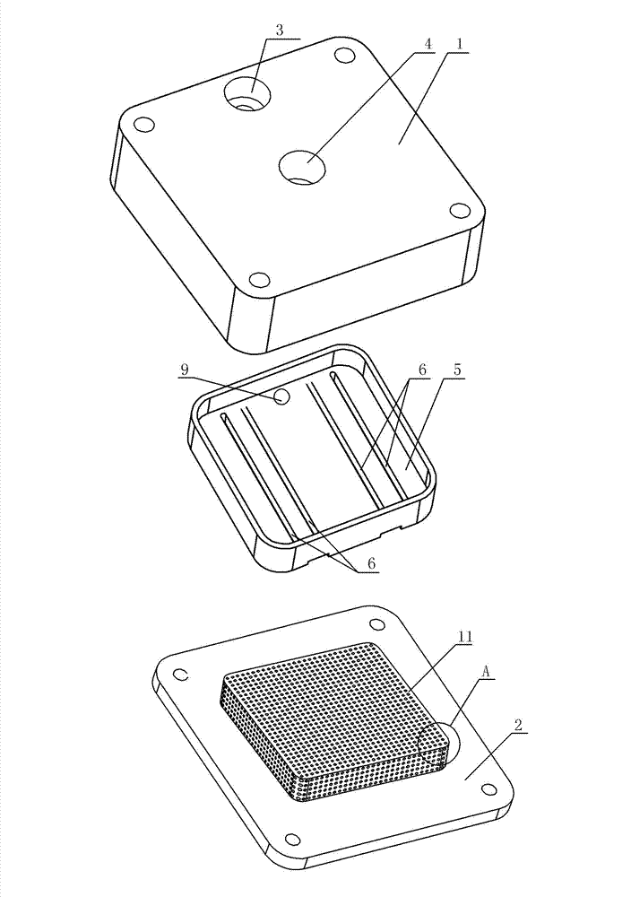
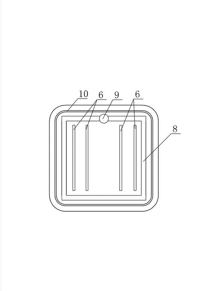
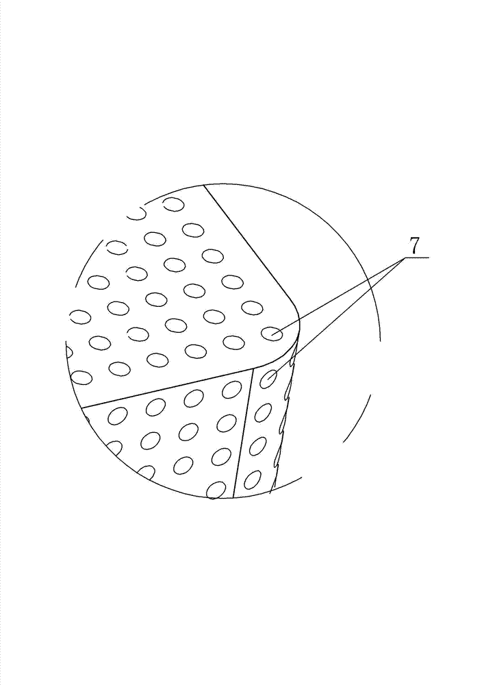
[0009] See figure 1 , figure 2 , image 3 , which includes an upper cover plate 1, a micro-cutting cooling plate 2, the upper end surface of the upper cover plate 1 is provided with a water outlet 3, a water inlet 4, the upper cover plate 1 is mounted on the micro-cutting cooling plate 2, the upper cover plate 1, the micro-cutting cooling plate The cavity formed by cutting the cooling plate 2 is provided with a jet splitter plate 5, the jet splitter plate 5 has four parallel flow channel notches 6, and the water inlet 4 is connected to the four parallel flow channels along the upper surface of the jet splitter plate 5. The channel notch 6, the bottom of the channel notch 6 is the heat dissipation bump 11 of the micro-cut cooling plate 2, and the heat dissipation bump 11 of the micro-cut cooling plate 2 is arranged with respective interconnected heat dissipation through holes 7, and the jet splitter plate The outer edge of the bottom of 5 is provided with a diversion groove ...


PUM


Abstract

The invention provides a multi-channel water-cooling structure of a CPU (central processing unit) of a computer. The multi-channel water-cooling structure of the CPU of the computer can reduce the temperature of a heating device to lower than the ambient temperature, is suitable for various environments and occasions with a large scope of application and can be used quietly without any noise. The multi-channel water-cooling structure of the CPU of the computer comprises an upper cover plate and a micro-cutting cooling plate, wherein a water outlet and a water inlet are arranged on the upper end face of the upper cover plate, the upper cover plate covers on the micro-cutting cooling plate, the multi-channel water-cooling structure of the CPU of the computer is characterized in that an injection spreader plate is arranged inside a cavity formed by the upper cover plate and the micro-cutting cooling plate, at least four parallel channel slots are arranged on the injection spreader plate, the water inlet is communicated with the parallel channel slots along the upper surface of the injection spreader plate, and heat dissipation bumps of the micro-cutting cooling plate are arranged below the channel slots.

Description

technical field [0001] The invention relates to the technical field of cooling of computer CPUs, in particular to a multi-channel water-cooling structure of computer CPUs. Background technique [0002] The current computer CPU cooling generally adopts two methods of air cooling and water cooling. With the continuous development of graphics card processing chips, the heat generated during the work process continues to increase. In order to ensure good heat dissipation performance and normal operation of the graphics card, Its air cooling must be cooled by a high-speed fan, which brings loud noise and vibration, which is annoying. However, in the existing water-cooling cooling method, the cooling effect of the water-cooling module can only reduce the temperature to the ambient temperature at most, which is not suitable for applications where the ambient temperature is relatively high, and its applicable range is small. Contents of the invention [0003] In view of the above...

Claims


Application Information

Patent Timeline
Patent Type & Authority Applications(China)
IPC IPC(8): H01L23/473G06F1/20
Inventor 谈士权
Owner WUXI FORMEN TECHN
Why Eureka
Try Eureka