Permanent magnet auxiliary synchronized reluctance motor rotor and motor thereof and installation method of motor

A technology for assisting synchronous and reluctance motors, which is applied to synchronous motors with stationary armatures and rotating magnets, electromechanical devices, and manufacturing motor generators. Problems such as the demagnetization current of the permanent magnets in each layer, to achieve the effect of improving operation reliability and anti-demagnetization ability

Inactive Publication Date: 2012-11-21
ZHUHAI GREE REFRIGERATION TECH CENT OF ENERGY SAVING & ENVIRONMENTAL PROTECTION
View PDF4 Cites 22 Cited by
  • Summary
  • Abstract
  • Description
  • Claims
  • Application Information

AI Technical Summary

Problems solved by technology

[0003] Generally speaking, improving the anti-demagnetization ability of the motor can be achieved by improving the performance of the permanent magnet material and increasing the thickness of the permanent magnet, but the above methods significantly increase the cost of the motor, and in some cases even if the permanent magnet with the best performance is used, If the thickest permanent magnet is used within the allowable range of the structure, the anti-demagnetization ability may not m

Method used


Image

  • Permanent magnet auxiliary synchronized reluctance motor rotor and motor thereof and installation method of motor
  • Permanent magnet auxiliary synchronized reluctance motor rotor and motor thereof and installation method of motor
  • Permanent magnet auxiliary synchronized reluctance motor rotor and motor thereof and installation method of motor

Examples


Embodiment Construction

[0026] The present invention will be described in detail below with reference to the accompanying drawings and examples. It should be noted that, in the case of no conflict, the embodiments in the present application and the features in the embodiments can be combined with each other.

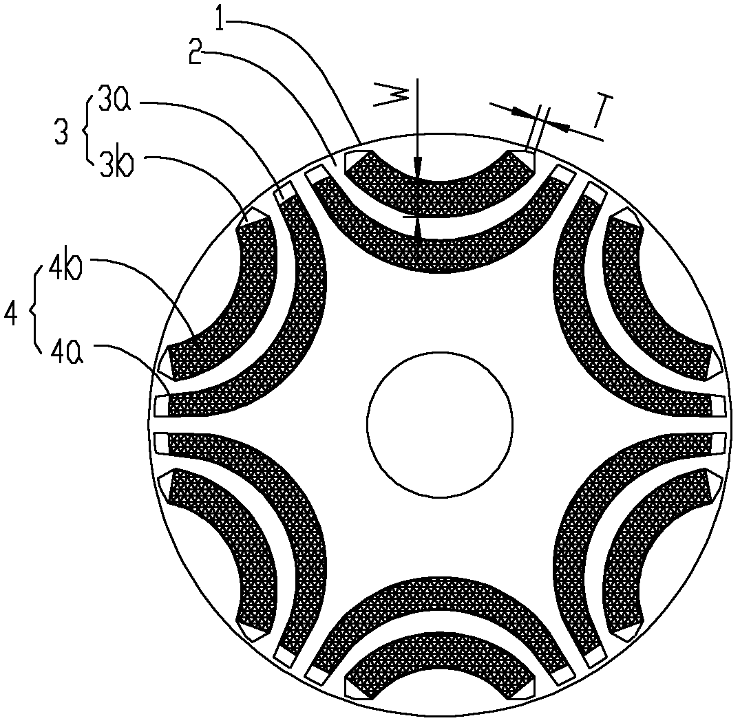
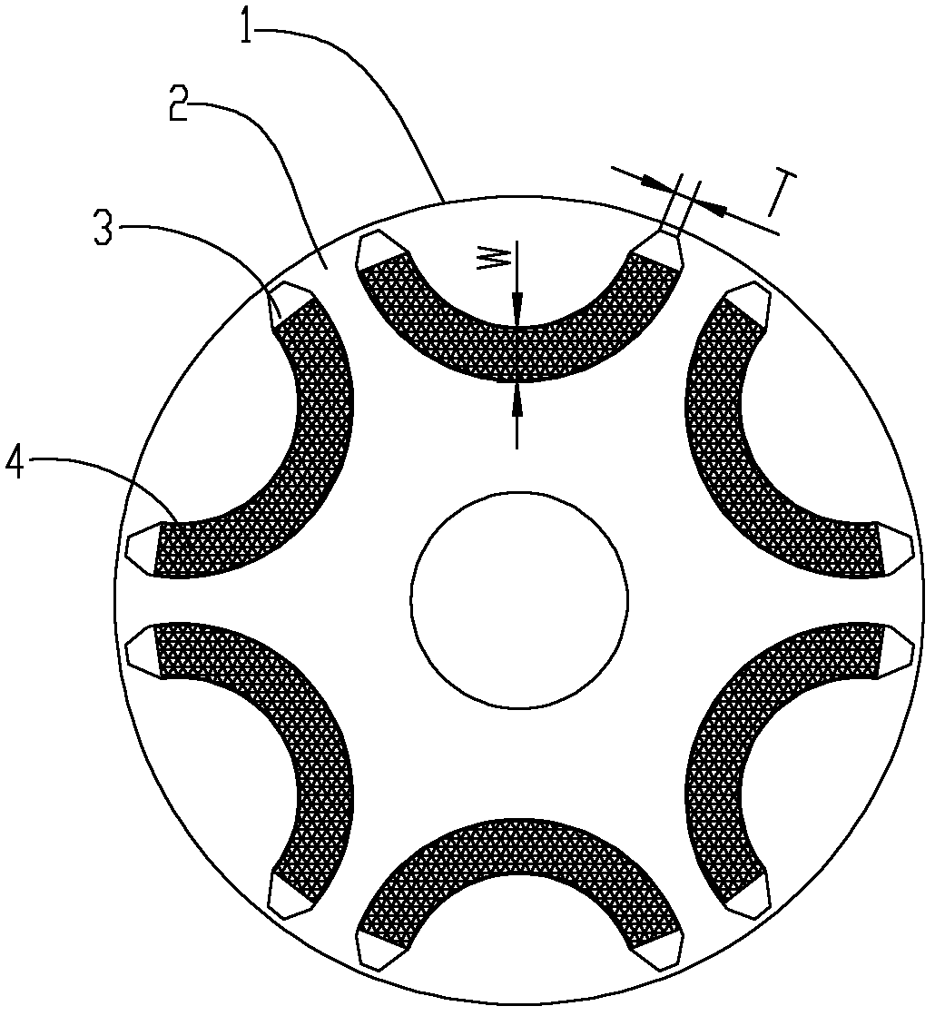
[0027] figure 1 The rotor of the permanent magnet assisted synchronous reluctance motor according to the first embodiment of the present invention is shown. The rotor has six permanent magnet groups, that is, six poles, each permanent magnet group has two layers of permanent magnets, and both the permanent magnet slots and the permanent magnets are arc-shaped. The following reference figure 1 and Figure 6 The first embodiment will be specifically described.

[0028] The rotor 1 of the permanent magnet assisted synchronous reluctance motor of the first embodiment includes a rotor core 2 and a plurality of permanent magnet groups. The rotor core 2 is made of laminated silicon steel plates. ...


PUM


Abstract

The invention provides a permanent magnet auxiliary synchronized reluctance motor rotor, a motor thereof and an installation method of the motor. The permanent magnet auxiliary synchronized reluctance motor rotor comprises a rotor iron core and a plurality of permanent magnet groups, a plurality of permanent magnet groove groups are uniformly distributed on the rotor iron core with rotor axis serving as a circle centre in a peripheral direction, each permanent magnet groove group comprises a single layer or multilayer of permanent magnet grooves, the number of the permanent magnet groups is identical to that of the permanent magnet groove groups, each permanent magnet group comprises a single layer or multilayer of permanent magnets which are respectively embedded into the permanent magnet grooves of the corresponding permanent magnet groove groups, the permanent magnets in each permanent magnet group have the same polarity, the polarities of the two adjacent permanent magnet groups are opposite, the end portion of at least one layer of permanent magnet groove in the plurality of permanent magnet groove groups is a sharpened end provided with a cutting face, and width T of the sharpened end cutting face of a permanent magnet groove with the sharpened end and middle width W meet the following relation. By means of the motor rotor, the motor thereof and the installation method of the motor, the whole demagnetization resistant capacity and operation reliability of the motor are improved.

Description

technical field [0001] The invention relates to the field of motors, and more specifically, to a rotor of a permanent magnet assisted synchronous reluctance motor, a motor thereof, and a method for installing the motor. Background technique [0002] In the permanent magnet assisted synchronous reluctance motor, because the permanent magnet is buried in the rotor iron core, the firmness of the rotor is enhanced, and the eddy current loss inside the permanent magnet is reduced. There are differences in inductance in the d-axis and q-axis directions of permanent magnet assisted synchronous reluctance motors. In addition to the permanent magnet torque of the motor, the reluctance torque of the motor can also be used to improve the efficiency of the motor, so its application is becoming more and more extensive. . However, the currently used permanent magnet motors have the risk of demagnetization under harsh conditions such as motor startup failure or out-of-step operation. Amon...

Claims


Application Information

Patent Timeline
IPC IPC(8): H02K1/27H02K21/14H02K15/00H02K15/03
Inventor 黄辉胡余生陈东锁肖勇曾学英
Owner ZHUHAI GREE REFRIGERATION TECH CENT OF ENERGY SAVING & ENVIRONMENTAL PROTECTION
Why Eureka
Try Eureka