Bistable composite cantilever beam piezoelectric power generating device

A composite cantilever beam and piezoelectric power generation technology, which is applied in the direction of generators/motors, piezoelectric effect/electrostrictive or magnetostrictive motors, electrical components, etc., can solve the problems of poor environmental adaptability, small power generation, and power generation efficiency. Low-level problems, to achieve the effect of wide operating frequency and increase power generation

Inactive Publication Date: 2012-11-21
TIANJIN UNIV
View PDF9 Cites 50 Cited by
  • Summary
  • Abstract
  • Description
  • Claims
  • Application Information

AI Technical Summary

Problems solved by technology

[0006] In view of the problems of poor environmental adaptability, low power generation efficiency, and small power generation per unit time of the current piezoelectric cantilever beam power generation device, in order to make the piezoelectric power generation device more adaptable to random, broadband, and low-frequency small-amplitude vibration ...

Method used


Image

  • Bistable composite cantilever beam piezoelectric power generating device
  • Bistable composite cantilever beam piezoelectric power generating device
  • Bistable composite cantilever beam piezoelectric power generating device

Examples


Embodiment

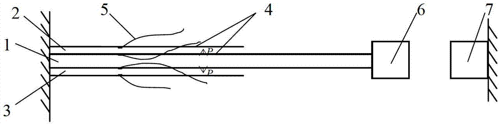
[0029] figure 1The structure of the bistable piezoelectric cantilever vibrator in the present invention is shown, including a bimorph piezoelectric cantilever beam 1, and the upper and lower surfaces of the bimorph piezoelectric cantilever beam 1 are respectively pasted with a first piezoelectric layer 2 and a second piezoelectric layer. Two piezoelectric layers 3; the first piezoelectric layer 2 and the second piezoelectric layer 3 have the same width as the elastic beam on the bimorph piezoelectric cantilever beam 1, and the first piezoelectric layer 2 and the second piezoelectric layer The length of the piezoelectric layer 3 is 60% of the length of the elastic beam. The polarization direction of the first piezoelectric layer 2 and the second piezoelectric layer 3 is along the thickness direction of the cantilever beam, such as figure 1 In the direction of the arrow shown in P, the piezoelectric layer is made of piezoelectric ceramic sheets, and electrodes 4 are plated on t...


PUM


Abstract

The invention discloses a bistable composite cantilever beam piezoelectric power generating device. The bistable composite cantilever beam piezoelectric power generating device comprises a casing, wherein a cylindrical clamp is fixed at the center in the casing; eight bistable piezoelectric cantilever oscillator structures are uniformly distributed on the clamp and are of an annular array; each bistable piezoelectric cantilever oscillator structure comprises a twin crystal bistable piezoelectric cantilever beam fixed on the clamp, a first piezoelectric layer, a second piezoelectric layer, a first permanent magnet and a second permanent magnet, wherein the first pieoelectric layer and the second pieoeelctric layer are respectively attached to the upper surface and the lower surface of the twin crystal bistable piezoelectric cantilever beam; the first permanent magnet is arranged at a free end of the twin crystal bistable piezoelectric cantilever beam; the second permanent magnet is arranged opposite to the first permanent magnet on the inner wall of the casing on the same side of the beam; electrodes are respectively arranged on the upper surfaces and the lower surfaces of the first piezoelectric layer and the second piezoelectric layer; eight bistable piezoelectric cantilever oscillator structures are arranged in two-to-two symmetrical way; and parameters of two mutually-symmetrical bistable piezoelectric cantilever oscillator structures are consistent. The work frequency domain width, the power generation efficiency and the power generation amount in unit time of the bistable composite cantilever beam piezoelectric power generating device are remarkably improved compared with a single piezoelectric cantilever beam structure and an array linear voltage cantilever beam structure.

Description

technical field [0001] The invention relates to a bistable composite cantilever beam piezoelectric power generation device, which can effectively collect the vibration mechanical energy of the surrounding environment for power generation, and belongs to the field of energy-saving technology and renewable and environmentally friendly new energy. Background technique [0002] With the increasing application of MEMS and portable electronic devices, the traditional way of using chemical batteries for power has exposed many disadvantages, such as short life, regular replacement, pollution of the environment, etc.; especially for harsh working conditions or places that are inaccessible to humans For electronic devices, battery replacement is expensive and difficult; therefore, how to power these electronic devices has become an urgent problem to be solved. Vibration energy in the surrounding environment can be converted into electrical energy by using the positive piezoelectric ef...

Claims


Application Information

Patent Timeline
IPC IPC(8): H02N2/18
Inventor 曹树谦郭抗抗孙舒
Owner TIANJIN UNIV
Why Eureka
Try Eureka