
Solar power generation device

A power generation device and solar cell technology, which is applied in the field of solar power generation, can solve the problems of short service life, falling off of the silver plating layer, time-consuming and manpower-consuming optical mirrors, etc., and achieve the goals of reducing splicing gaps, prolonging service life, and improving utilization efficiency Effect

Active Publication Date: 2012-11-21
JIANGSU ENEUTRAL NEW ENERGY TECH CO LTD
View PDF3 Cites 2 Cited by
  • Summary
  • Abstract
  • Description
  • Claims
  • Application Information

AI Technical Summary

Problems solved by technology

In order to ensure that the concentrated light spot at the focal point is small enough so that the light spot can be completely projected onto the solar cell, the area of ​​the reflective mirror must be small enough. At present, the area of ​​the reflective mirror is basically 1 square centimeter, which makes the processing process of the entire optical reflector very difficult. time and manpower
Moreover, the weather resistance of the light reflector formed by the above method is also relatively poor.
After a long period of use, dust will inevitably accumulate in the gaps between the small reflectors, and the silver-plated layer on the back of the mirror is easily eroded by rain, wind and sand and falls off, which affects the light-gathering effect of the light reflector and has a short service life.

Method used


Image

  • Solar power generation device

Examples


Embodiment Construction

[0021] The present invention will be further described in detail below in conjunction with the accompanying drawings, so that those skilled in the art can implement it with reference to the description.

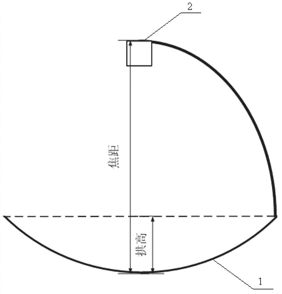
[0022] like figure 1 As shown, the present invention provides a solar power generation device, including: a light reflector 1, which is in the shape of a paraboloid of revolution, and the paraboloid of revolution follows the formula y=x 2 / 4f, wherein, f is the focal length of the paraboloid of revolution, and the light reflector is composed of 1 to 6 reflector surfaces; the solar cell 2 is arranged at the focal point of the light reflector.

[0023] In the solar power generation device described above, the light reflector is composed of a reflective mirror surface integrally molded at one time.

[0024] In the solar power generation device, the ratio of the area of ​​the light reflecting mirror to the area of ​​the solar cell is less than or equal to 1000.

[0025] In the ...


PUM


Abstract

The invention discloses a solar power generation device, which comprises a light reflector and a solar cell; the light reflector is shaped like a paraboloid of revolution, the paraboloid of revolution abides by a formula (y equal to x2 / 4f), wherein f is the focus of the paraboloid of revolution, and the light reflector consists of one to six reflecting surfaces; and the solar cell is arranged at the position of the focus of the light reflector. Since the light reflector is shaped like the paraboloid of revolution and consists of one to six reflecting surfaces, the connecting gaps between the small reflecting surfaces are reduced, the diameter of the condensed light spot at the focus is less than 5mm, the sunlight utilization efficiency of the solar power generation device is greatly increased, and meanwhile, the service life of the light reflector is greatly prolonged. Since the solar cell is arranged at the position of the focus of the light reflector, light is reflected only once; meanwhile, since the weather fastness of the light reflector is greatly enhanced and the service life of the light reflector is greatly prolonged, the light reflector can be exposed in the outside environment, and thereby the energy utilization efficiency of the solar power generation device is increased.

Description

technical field [0001] The invention relates to the field of solar power generation, in particular to a solar power generation device. Background technique [0002] In the prior art, the manufacturing process of the optical reflector is to manually paste small reflector surfaces on the parabolic substrate. In order to ensure that the concentrated light spot at the focal point is small enough so that the light spot can be completely projected onto the solar cell, the area of ​​the reflective mirror must be small enough. At present, the area of ​​the reflective mirror is basically 1 square centimeter, which makes the processing process of the entire optical reflector very difficult. time and manpower consuming. Moreover, the weather resistance of the optical reflector formed by the above method is also poor. After a long period of use, dust will inevitably accumulate in the gaps between the small reflecting mirrors, and the silver-plated layer on the back of the mirror is ea...

Claims


Application Information

Patent Timeline
Patent Type & Authority Applications(China)
IPC IPC(8): H02N6/00H01L31/052H02S40/22
CPCY02E10/52
Inventor 李子京
Owner JIANGSU ENEUTRAL NEW ENERGY TECH CO LTD
Learn More