Forming device and forming method for corrugated foil of metal honeycomb core

A metal honeycomb core and foil technology, applied in the field of corrugated foil forming devices, can solve the problems of reducing the bearing strength of the metal honeycomb core, complicated stamping process, thinning, etc., to optimize the forming principle and structure, and realize automatic production. , the effect of reducing complexity

Active Publication Date: 2012-11-28
SHENZHEN INST OF ADVANCED TECH CHINESE ACAD OF SCI
View PDF7 Cites 10 Cited by
  • Summary
  • Abstract
  • Description
  • Claims
  • Application Information

AI Technical Summary

Problems solved by technology

[0005] For the first type of semi-regular hexagonal corrugated foil forming (rolling forming), since the tooth shape of the forming roller is a non-involute tooth shape, the transmission is discontinuous and unstable during the meshing of the roller teeth, and there is a large local presence in the movement. The gap between the upper bottom and the hypotenuse of the formed semi-regular hexagonal foil lattice is smaller than the angle between the bottom and the hypotenuse, and there is obvious arc bending, which is not conducive to the subsequent manufacturing process of the metal honeycomb core. Complete, and there are obvious extrusion marks near the corners of each tooth top and tooth root, which reduces the quality of the semi-regular hexagonal corrugated foil, thus directly affecting the bearing strength of the metal honeycomb core
For the second type of forming device (stamping forming), due to the small and dense lattice unit of the semi-regular hexagonal corrugated foil, the stamping process is complicated, the precision of the stamping mechanism is high, the stamping efficiency is low, and it is difficult to realize full automation. The thickness of some parts of the semi-regular hexagonal corrugated foil has obvious thinning phenomenon, which reduces the bearing strength of the metal honeycomb core

Method used


Image

  • Forming device and forming method for corrugated foil of metal honeycomb core
  • Forming device and forming method for corrugated foil of metal honeycomb core
  • Forming device and forming method for corrugated foil of metal honeycomb core

Examples


Embodiment Construction

[0047]In order to facilitate the understanding of the present invention, the present invention will be described more fully below with reference to the associated drawings. Preferred embodiments of the invention are shown in the accompanying drawings. However, the present invention can be embodied in many different forms and is not limited to the embodiments described herein. On the contrary, these embodiments are provided to make the understanding of the disclosure of the present invention more thorough and comprehensive.

[0048] It should be noted that when an element is referred to as being “fixed” to another element, it can be directly on the other element or there can also be an intervening element. When an element is referred to as being "connected to" another element, it can be directly connected to the other element or intervening elements may also be present. The terms "vertical," "horizontal," "left," "right," and similar expressions are used herein for purposes o...


PUM


Abstract

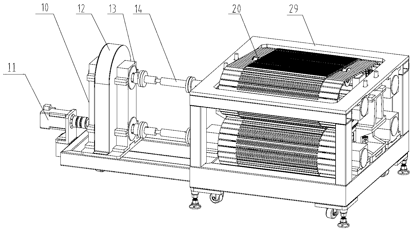
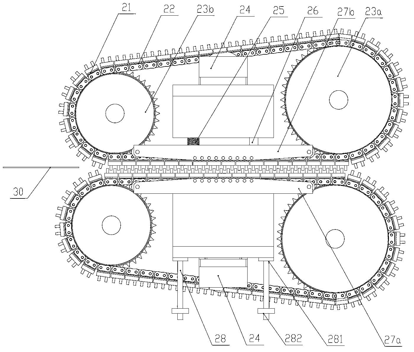
The invention provides a forming device and a forming method for a corrugated foil of a metal honeycomb core. The forming device comprises a frame and two forming mechanisms, wherein two forming mechanisms are vertically arranged in the frame in parallel, each forming mechanism mainly comprises a drive chain wheel rotatably arranged on the frame, a driven chain wheel rotatably arranged on the frame and spaced with the driven chain wheel, a chain sheathed on the drive chain wheel and the driven chain wheel, multiple forming toothed bars connected with the chain in sequence through chain accessories, a tension device docked with the inner side of the chain so as to tense the chain through the tension device, a slide guide mechanism located at the inner side of the chain, a pressure application device arranged on one end of the slide guide mechanism, and a setting device arranged on the other end of the slide guide mechanism. According to the forming device and the forming method, the forming efficiency is improved, the forming quality is ensured, the complexity of the forming device is reduced, and automatic production of forming of the corrugated foil is realized.

Description

【Technical field】 [0001] The invention relates to a forming device and method for a corrugated foil material, in particular to a forming device and method for a corrugated foil material with a metal honeycomb core. 【Background technique】 [0002] One of the key technologies for manufacturing high-density metal honeycomb cores by forming method lies in the forming quality of the semi-regular hexagonal corrugated foil, which directly affects the quality of the formed metal honeycomb. If the semi-regular hexagonal corrugated foil The forming quality of corrugated foil is so poor that it is even difficult to form high-density metal honeycomb. On the basis of the traditional forming method for manufacturing semi-regular hexagonal corrugated foils, this invention proposes a set of forming devices that integrate the forming and shaping of semi-regular hexagonal corrugated foils, which effectively solves the problem of low forming precision and forming quality in traditional forming...

Claims


Application Information

Patent Timeline
Patent Type & Authority Applications(China)
IPC IPC(8): B21D33/00
Inventor 于文泽罗昌杰梅明王书付刘天宝何凯杜如虚
Owner SHENZHEN INST OF ADVANCED TECH CHINESE ACAD OF SCI
Why Eureka
Try Eureka