
a tractor

The technology of a tractor and a tractor is applied to the tractor. It can solve the problems of the traction head protruding from the track, the traction power is large, and the safety is poor, so as to achieve the effect of good starting control performance, low traction power, and easy maintenance.

Active Publication Date: 2017-06-20
FOSHAN JINHANYUE HAIHANG MACHINERY EQUIP
View PDF6 Cites 0 Cited by
  • Summary
  • Abstract
  • Description
  • Claims
  • Application Information

AI Technical Summary

Problems solved by technology

[0005] C. High failure rate: As mentioned in point B above, the driving device of the pallet opening and closing mechanism and the pressure claw lifting mechanism and its electrical control box are all installed on the traction head running at high speed. Due to the vibration and impact during the operation, the driving device, Inductive switches, electrical components in the box, etc. are prone to failure, and the control of the pallet pressing claw by the main control cabinet is realized through the sliding contact wire and collector with high failure rate. The failure of parts and trolley line collectors has become a high-incidence area for the failure of the entire traction machine
[0006] D. Large traction power and high energy consumption: As mentioned in point B above, due to the large weight of the traction head, the traction power to be configured is relatively large, and the energy consumption also increases accordingly
[0007] E. Poor safety: As mentioned in point B above, many mechanisms are installed on the tractor head, so the volume of the tractor head is large, which makes the volume of the tractor head protrude from the track. Due to the danger of high-speed operation of the tractor head, safety management is difficult. Very prone to safety accidents
[0008] To sum up, the current tractors can no longer meet the requirements of enterprises in terms of accuracy, structure, failure rate, traction work or safety. direction

Method used


Image

  • a tractor
  • a tractor
  • a tractor

Examples


Embodiment Construction

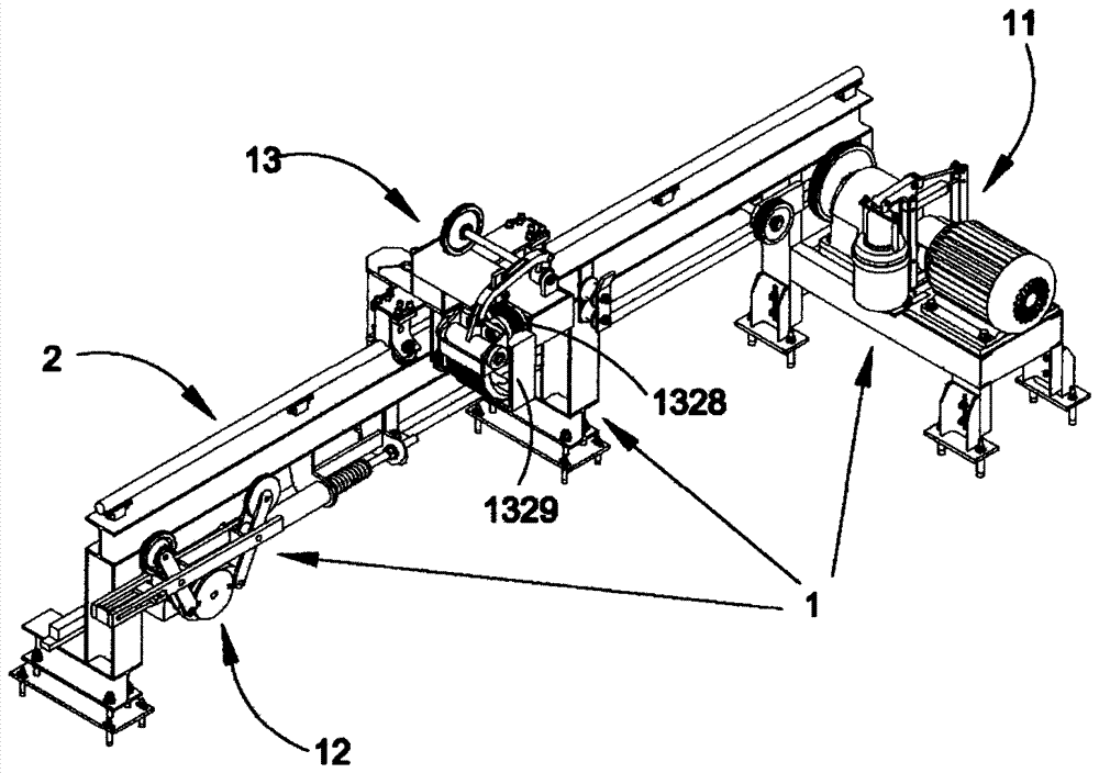
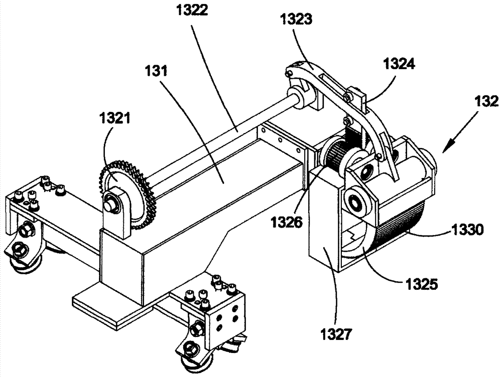
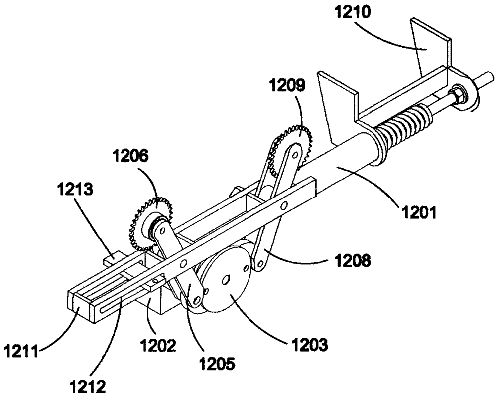
[0026] Such as Figure 1 to Figure 5 Shown is a preferred specific implementation example of the present invention, a tractor includes a traction unit 1 and a track 2, wherein the traction unit 1 includes a traction force power device 11, a material clamping power mechanism 12 and a traction head 13, the The traction head 13 is made up of a frame 131 and a clamping mechanism 132 installed on the frame 131 .

[0027] The traction power unit 11 is placed on one side of the track 2, and the traction power unit 11 is in transmission connection with the frame 131 on the traction head 13, and the frame 131 of the traction head 13 is slidably connected to the track 2. The material clamping power mechanism 12 is installed on the track 2 , and the material clamping power mechanism 12 is in transmission connection with the material clamping mechanism 132 of the traction head 13 .

[0028] Such as Figure 1 to Figure 2 As shown, the clamping mechanism 132 includes a first transmission ...


PUM


Abstract

The invention provides a tractor, which structurally includes a traction unit and a track; The material clamping mechanism is composed; the traction power device is placed on one side of the guide rail, and the gravity power device is connected with the frame of the traction head in transmission, and the frame of the traction head is also slidingly connected on the track; the material clamping power mechanism Installed on the guide rail and the material clamping power mechanism is connected with the material clamping mechanism of the traction head. The unique design structure of the present invention realizes low failure rate, small impact, stable operation, good start-up control performance and Low power consumption, low traction power, low energy consumption, and easy maintenance. In addition, the present invention also has the advantages of simple structure, light weight and convenient use.

Description

technical field [0001] The invention relates to a traction device, more specifically to a traction machine. Background technique [0002] After years of development, there are many varieties and types of tractors, mainly composed of rails, traction heads, traction power devices, automatic interrupt saws, electrical control systems, etc., and all have shortcomings, as follows: [0003] A. Poor guide precision of track: Due to the short section distance and difficult installation and adjustment of various forms of track, the installation accuracy is poor, resulting in a large swing range at the clamping position of the tractor head, which reduces the surface quality of the profile. [0004] B. The traction head is heavy: the current clamping device has two mechanisms, the pallet opening and closing mechanism and the claw lifting mechanism. These two mechanisms are controlled separately by the electrical system during the work process, so that they work sequentially. Actions t...

Claims


Application Information

Patent Timeline
Patent Type & Authority Patents(China)
IPC IPC(8): B23Q3/00B23Q7/00
Inventor 关灿彬
Owner FOSHAN JINHANYUE HAIHANG MACHINERY EQUIP
Learn More