Cyclone airlift fermentation tank

A fermenter and gas flow technology, which is applied in the field of swirling air-lift fermenter, can solve the problems of poor energy saving effect of non-stirred fermenter, inability to apply fermenter, and influence on growth and metabolism, and achieve good gas-liquid mixing effect and gas-liquid mixing Low consumption, high efficiency and high fermentation efficiency

Active Publication Date: 2012-11-28
陆飞浩
View PDF6 Cites 18 Cited by
  • Summary
  • Abstract
  • Description
  • Claims
  • Application Information

AI Technical Summary

Problems solved by technology

However, in order to transform the high-speed jet flow, the pressure of the air entering the tank is required to be higher than the pressure required by the common ventilated fermentation tank with stirring. Therefore, although the power consumption of stirring is saved, the increase of the outlet pressure of the air compressor leads t

Method used


Image

  • Cyclone airlift fermentation tank
  • Cyclone airlift fermentation tank
  • Cyclone airlift fermentation tank

Examples


Embodiment Construction

[0019] The present invention will be further described in detail below in conjunction with the accompanying drawings and embodiments.

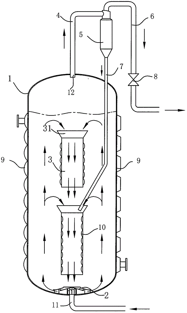
[0020] like figure 1 As shown, a swirling airlift fermenter comprises a cylindrical vertical tank body 1, an air intake device, an exhaust device, a flow guiding device and a cooling device, and the tank body 1 is provided with an air intake pipe 11, Exhaust pipe 4 and various necessary pipeline interfaces, the air intake pipe 11 is located at the center of the bottom of the tank body 1 or near the center of the bottom of the tank body 1, and is connected with the air intake device, and the exhaust pipe 4 is provided with The central position on the top of the tank body 1 is connected with the exhaust device.

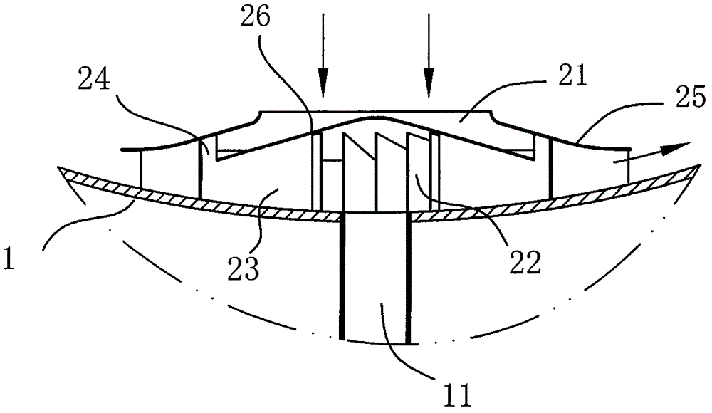
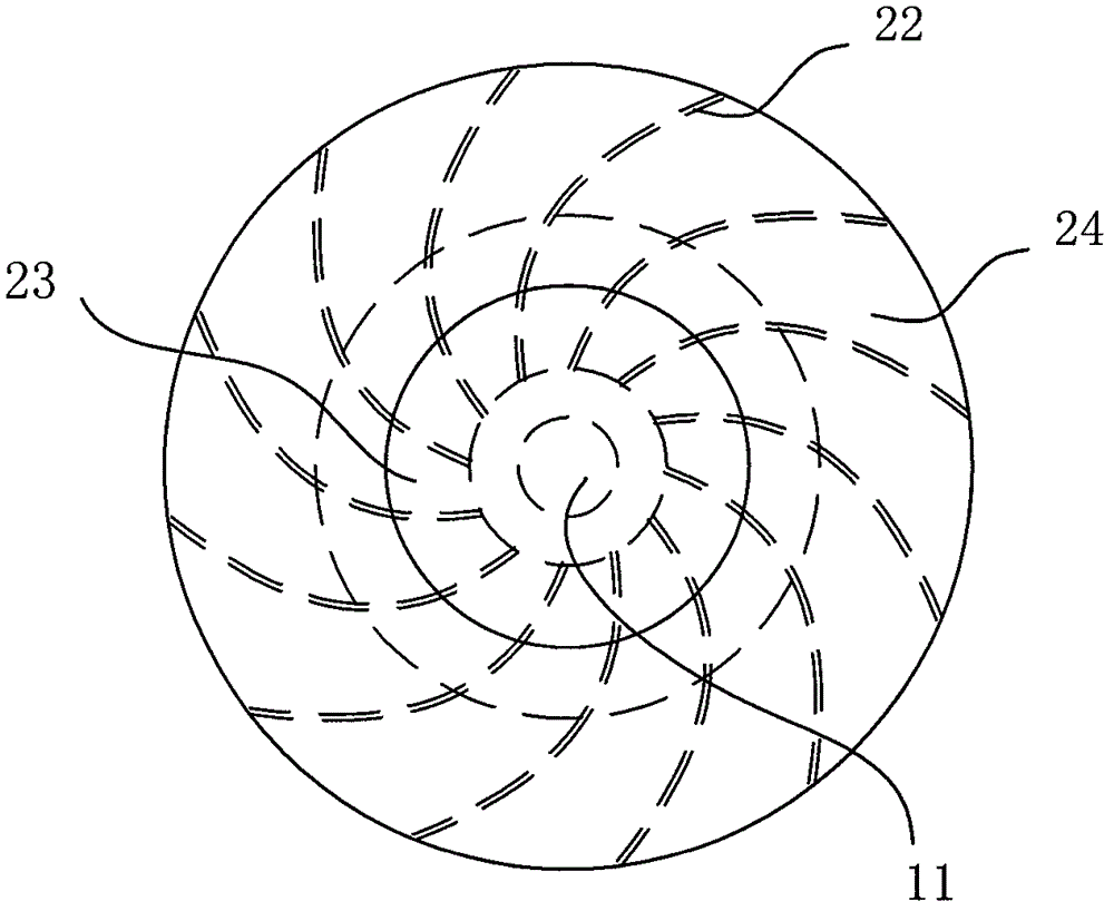
[0021] like Figure 2a , 2b As shown, the air intake device is a swirl mixer 2, which is arranged at the bottom of the tank body 1, installed close to the lower head of the tank body 1 and connected to the air inlet pipe 11, and the ...


PUM


Abstract

The invention discloses a cyclone airlift fermentation tank. The cyclone airlift fermentation tank comprises a tank body, an air inlet device, an exhaust device, a cooling device, and an air inlet pipe and an exhaust pipe which are arranged on the tank body, wherein the air inlet pipe is connected with the air inlet device; and the exhaust pipe is connected with the exhaust device. The cyclone airlift fermentation tank is characterized in that the air inlet pipe is arranged at the middle position of the bottom of the tank body or a position which is close to the bottom of the tank body; the exhaust pipe is arranged at the middle position of the top of the tank body; the air inlet device is a cyclone mixer, is arranged at the bottom in the tank body or a position which is close to the bottom of the tank body, and is connected with the air inlet pipe; and a flow guiding device is arranged above the cyclone mixer, has a cylindrical structure with two open ends, and is longitudinally arranged on the axis of the tank body. The cyclone airlift fermentation tank has a concise structure, is relatively low in aeration pressure, but can ensure that gas and liquid are in a cyclone state, has a good gas-liquid mixing effect, is low-consumption and efficient, can exhaust cleanly, is high in fermentation efficiency, and is applicable to the submerged fermentation of aerobic microorganisms, and a stirring device is not arranged.

Description

technical field [0001] The invention relates to a fermenter, in particular to a swirling air-lift fermenter used in large-scale industrial production as an aerobic microbial fermentation. Background technique [0002] Usually, the aerobic microbial fermentation tank has a stirring system, a cooling system, and a ventilation and exhaust device inside. With the continuous expansion of industrial mass production fermentation scale, the diameter and height of a single fermentation tank have also doubled. The diameter of the fermenter has increased from 2m to 4m in the past to the current 4m to 10m; the height has increased from the past 5m to 10m to the current 10m to 20m. Since the stirring power is proportional to the square of the diameter of the stirrer, the stirring power doubles after the volume of the fermenter is enlarged, resulting in a substantial increase in energy consumption. [0003] In order to reduce energy consumption, a variety of vertical non-stirring fermen...

Claims


Application Information

Patent Timeline
IPC IPC(8): C12M1/00C12M1/04
CPCC12M29/08C12M29/20C12M27/24
Inventor 陆飞浩
Owner 陆飞浩
Why Eureka
Try Eureka