Method used for improving measuring accuracy of point-diffraction interferometer

A point-diffraction interferometer and a technology for testing accuracy, which is applied in the field of point-diffraction interferometer testing, can solve the problems of point-diffraction interferometer test accuracy drop, camera can not be saturated, edge image analog-to-digital conversion digits drop, etc., to achieve easy processing and manufacturing , improve the test accuracy, the effect of simple design structure

Inactive Publication Date: 2012-11-28
CHANGCHUN INST OF OPTICS FINE MECHANICS & PHYSICS CHINESE ACAD OF SCI
View PDF5 Cites 14 Cited by
  • Summary
  • Abstract
  • Description
  • Claims
  • Application Information

AI Technical Summary

Problems solved by technology

Since the point diffraction interferometer generally uses a camera as the sensor for collecting interference fringes, analog-to-digital conversion is required between it and the control computer. The camera must not be saturated when co...

Method used


Image

  • Method used for improving measuring accuracy of point-diffraction interferometer
  • Method used for improving measuring accuracy of point-diffraction interferometer
  • Method used for improving measuring accuracy of point-diffraction interferometer

Examples


Embodiment Construction

[0015] The present invention will be described in further detail below in conjunction with the accompanying drawings and embodiments.

[0016] A method for improving the test accuracy of a point diffraction interferometer, the method comprising the steps of:

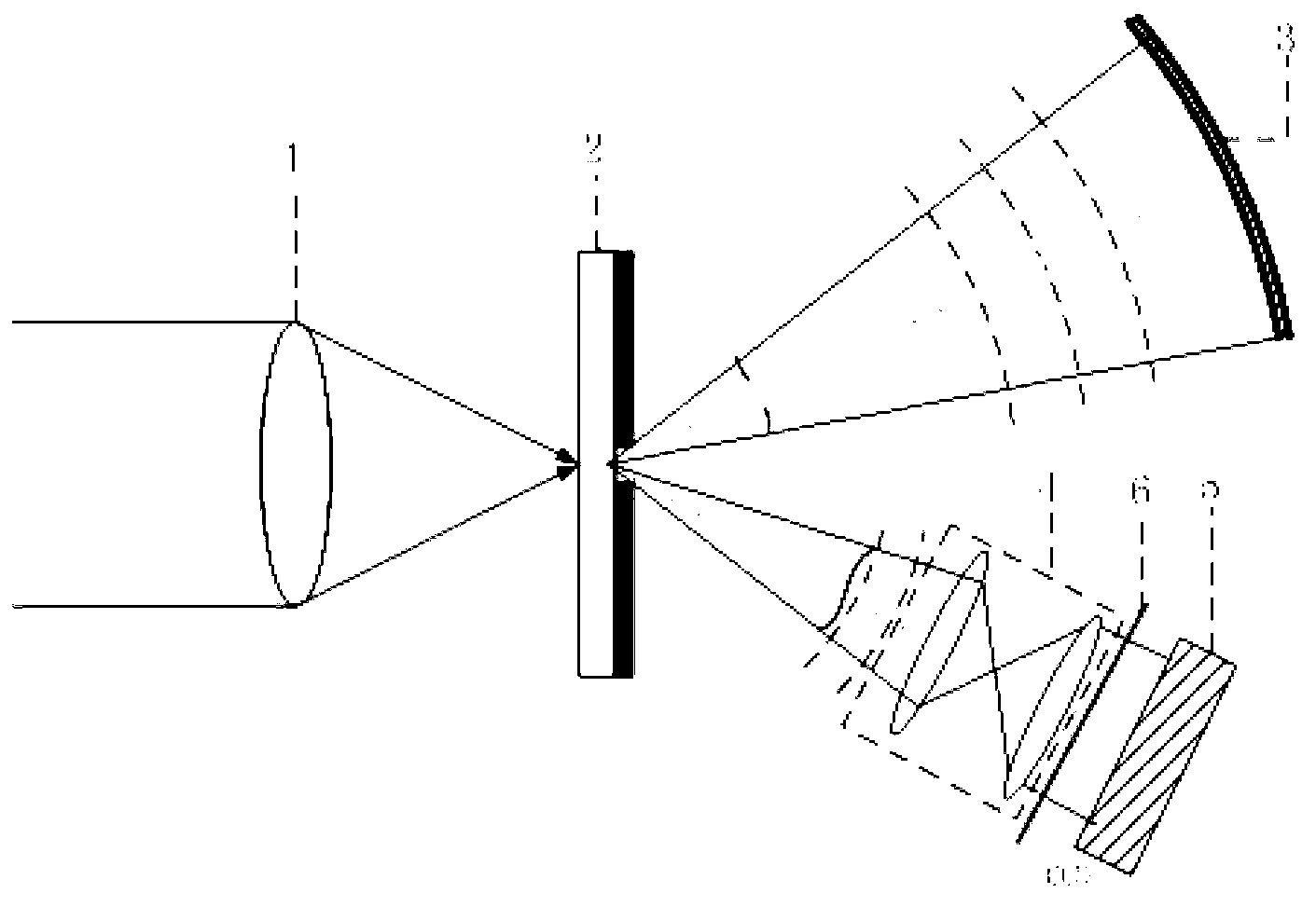
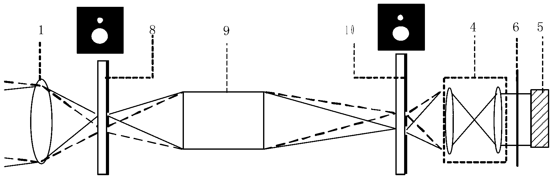
[0017] Step 1: Place the converging lens and the small orifice plate on the same optical axis, the parallel light source is converged by the converging lens, and exits through the small orifice plate, part of the light forms the test light, and the other part of the light is used as the reference light; the test light and reference light are imaged by the camera The common light path at the exit pupil of the lens;

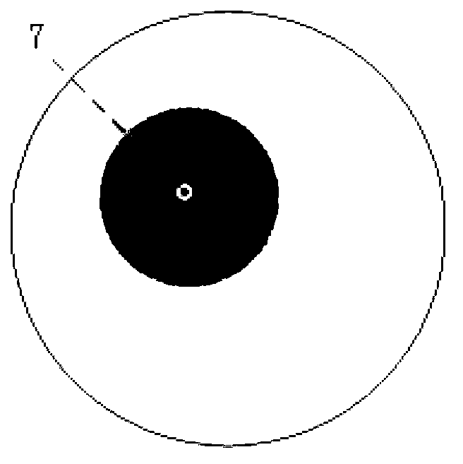
[0018] Step 2: Record the maximum value of the exit pupil light intensity at the exit pupil of the imaging lens as A, and place an attenuation sheet centered at point A, with gradually increasing transmittance along the radial direction, to adjust the exit pupil beam of the imaging lens The intensity distrib...


PUM


Abstract

The invention relates to a method used for improving measuring accuracy of a point-diffraction interferometer, and belongs to the test field of point-diffraction interferometers. The method comprises the following steps of: placing a gathering lens and a foraminule plate on a same optical axis, enabling a parallel light source to gather through the gathering lens, and exit through the foraminule plate; enabling part of rays to form testing light, enabling the other part of rays to be used as reference light, and enabling the testing light and the reference light to share a light path on an ocular circle position of an imaging lens of a camera; and marking the light intensity maximum value of ocular circle on the ocular circle position of the imaging lens as A, placing an attenuation piece for which A point is taken as a centre and the transmissibility is gradually improved, wherein the attenuation piece is used for adjusting the light intensity distribution of an ocular circle light beam of the imaging lens, and the image intensities of the centre and an edge interference fringe are consistent. The method provided by the invention has the advantages that the design and structure are simple, the cost is cheap, the processing and manufacturing are easy, the problem that the rim light intensity of the point-diffraction interferometer is dropped so as to cause analog-digital conversion digit reduction is solved with lower cost, and the measuring accuracy of the point-diffraction interferometer is improved.

Description

technical field [0001] The invention belongs to the field of point-diffraction interferometer testing, and in particular relates to a method for improving the testing precision of a point-diffraction interferometer. Background technique [0002] Interferometer is a kind of high-precision optical measurement equipment. Among them, the point diffraction interferometer uses the wavefront diffracted by the small hole as the test reference wavefront, which has high precision and has been used in ultra-high-precision optical detection and measurement. . Due to the small hole diffraction of the point diffraction interferometer, the light intensity distribution of the spherical beam emitted by it is uneven, and the light intensity and brightness of the central area are significantly higher than that of the edge area. In this way, when the point diffraction interferometer tests optical components and optical systems with high numerical aperture, the brightness of the edge of the int...

Claims


Application Information

Patent Timeline
IPC IPC(8): G01B9/02G01J9/02
Inventor 邵晶马冬梅张海涛于杰
Owner CHANGCHUN INST OF OPTICS FINE MECHANICS & PHYSICS CHINESE ACAD OF SCI
Why Eureka
Try Eureka