Reflecting color filter

A color filter and reflective technology, which is applied in optics, optical components, instruments, etc., can solve the problems of high hazards to operators and the environment, and fewer reflective color filters, so as to achieve insensitivity to color changes and reflective The effect of low rate and high color purity

Inactive Publication Date: 2012-11-28
SUZHOU UNIV +1
View PDF6 Cites 20 Cited by
  • Summary
  • Abstract
  • Description
  • Claims
  • Application Information

AI Technical Summary

Problems solved by technology

The problem is that the ink contains harmful substances such as aromatic hydrocarbons, heavy metals, benzene, and ketones, which are very harmful to operators and the environment during the produ

Method used


Image

  • Reflecting color filter
  • Reflecting color filter
  • Reflecting color filter

Examples


Embodiment 1

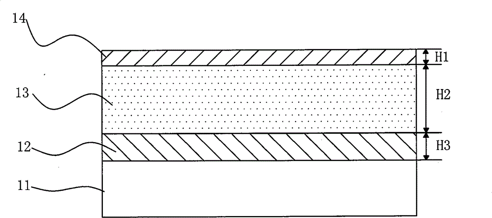
[0029] 31 is the flexible material PET or PC, 32 is aluminum, 33 is PMMA, 34 is nickel and 35 is PMMA.

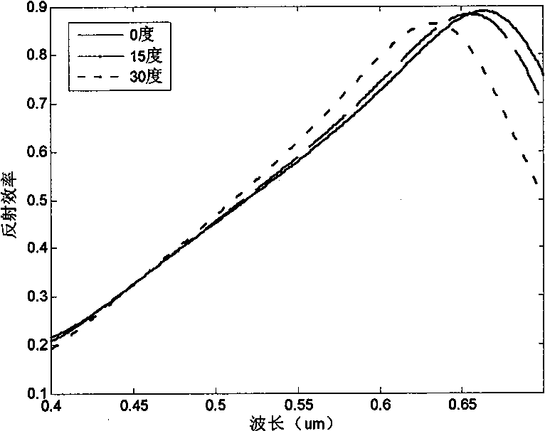
[0030] The structural parameters are designed for red, green and blue reflective color filters. Red: p=0.3um, F=0.3, h1=0.03um, h2=0.2um, h3=0.4um, h4=0.02um, h5=0.4um; Green: p=0.35um, F=0.5, h1=0.03 um, h2=0.18um, h3=0.35um, h4=0.01um, h5=0.35um; blue: p=0.35um, F=0.5, h1=0.03um, h2=0.14um, h3=0.29um, h4 =0.01um, h5=0.25um. The reflection characteristics and angle sensitivity of the filter were analyzed by rigorous coupled wave theory (RCWA). TM polarized light is incident from the top of the structure at an angle ranging from 0° to 30°.

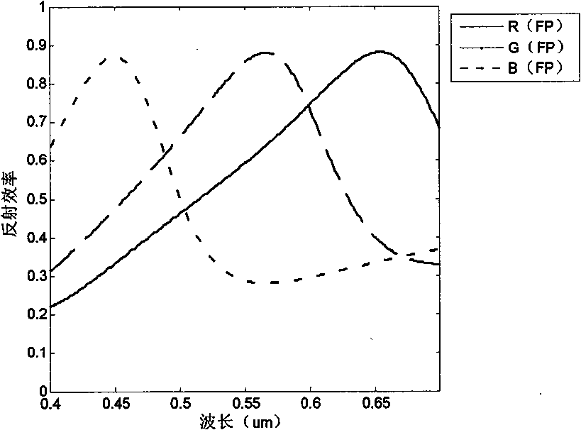
[0031] Figure 5 Among them, R(FP), G(FP), and B(FP) represent the reflection of red, green, and blue TM light based on the traditional Fabry-Perot (FP) cavity structure reflective color filter, respectively. Efficiency vs. incident wavelength plot. Figure 5 Among them, R, G, and B respectively represent the relationship diagrams...

Embodiment 2

[0034] Adjust the period p of the wire grid, and observe the influence of period change on the reflection characteristics of the filter. Take the red filter as an example. p=0.3um, F=0.3, h1=0.03um, h2=0.2um, h3=0.4um, h4=0.02um, h5=0.4um. The reflective properties of the filter are analyzed by rigorous coupled wave theory (RCWA). TM polarized light is incident from the top of this structure, and the incident angle of this light is 0 degrees. From Figure 7 It can be seen that the period has an impact on the reflection peak position and bandwidth, but the impact is very small.

Embodiment 3

[0036] Adjust the duty ratio F of the wire grid, and observe the influence of the duty ratio change on the reflection characteristics of the filter. Take the red filter as an example. p=0.25um, h1=0.03um, h2=0.2um, h3=0.4um, h4=0.02um, h5=0.4um. The reflective properties of the filter are analyzed by rigorous coupled wave theory (RCWA). TM polarized light is incident from the top of this structure at an incident angle of 0 degrees. From Figure 8 It can be seen that the duty ratio has an impact on the reflection peak position and bandwidth, but the impact is very small.


PUM

PropertyMeasurementUnit
Thicknessaaaaaaaaaa
Thicknessaaaaaaaaaa

Abstract

The invention relates to a reflecting color filter, which comprises a substrate, a high-reflecting metal layer, a resonant cavity layer and a half-reflecting and half-transmitting metal layer, wherein an interface part of the resonant cavity layer and the half-reflecting and half-transmitting metal layer has a wire grating structure; the half-reflecting and half-transmitting metal layer covers the wire grating structure to form a metal grating; and the period of the metal grating is less than 400 nm. By adjusting parameters such as the thickness of a wire grating resonant cavity, the radio of the width to the period of a wire grating, the thickness of a reflecting layer 2 and the thickness of a coverage layer, the reflecting color filter which is low in angle sensitivity, appropriate in bandwidth and low in sideband reflectivity can be obtained, and the reflecting filtration of different colors can be realized.

Description

technical field [0001] The invention relates to an optical filter element, in particular to a reflective color filter, which can be applied to the field of ink-free printing. Background technique [0002] The traditional printing technology is to print images and colors on the surface of paper, plastic and other materials through inks of different colors. The problem is that the ink contains harmful substances such as aromatic hydrocarbons, heavy metals, benzene, and ketones, which are very harmful to operators and the environment during the production and printing of the ink. Therefore, in recent years, the world has begun to advocate green and environmentally friendly ink-free printing. [0003] Due to the micro-nano structure on the surface of butterfly wings in nature, they show colorful colors that change with the viewing angle. A similar phenomenon of producing color without pigments has been observed on nanostructured metal gratings. These phenomena have given peop...

Claims


Application Information

Patent Timeline
IPC IPC(8): G02B5/26G02B1/10
Inventor 周云陈林森申溯叶燕浦东林周小红方宗豹张恒魏国军胡进
Owner SUZHOU UNIV
Why Eureka
Try Eureka