An infrared touch screen
A technology of infrared touch screen and infrared emission, which is applied in instruments, computing, electrical and digital data processing, etc., can solve the problems of poor touch effect in the corner area, few scanning lines, and inability to scan, so as to save costs, improve the corner effect, The effect of increasing density
- Summary
- Abstract
- Description
- Claims
- Application Information
AI Technical Summary
Problems solved by technology
Method used
Image

Examples
Embodiment 1
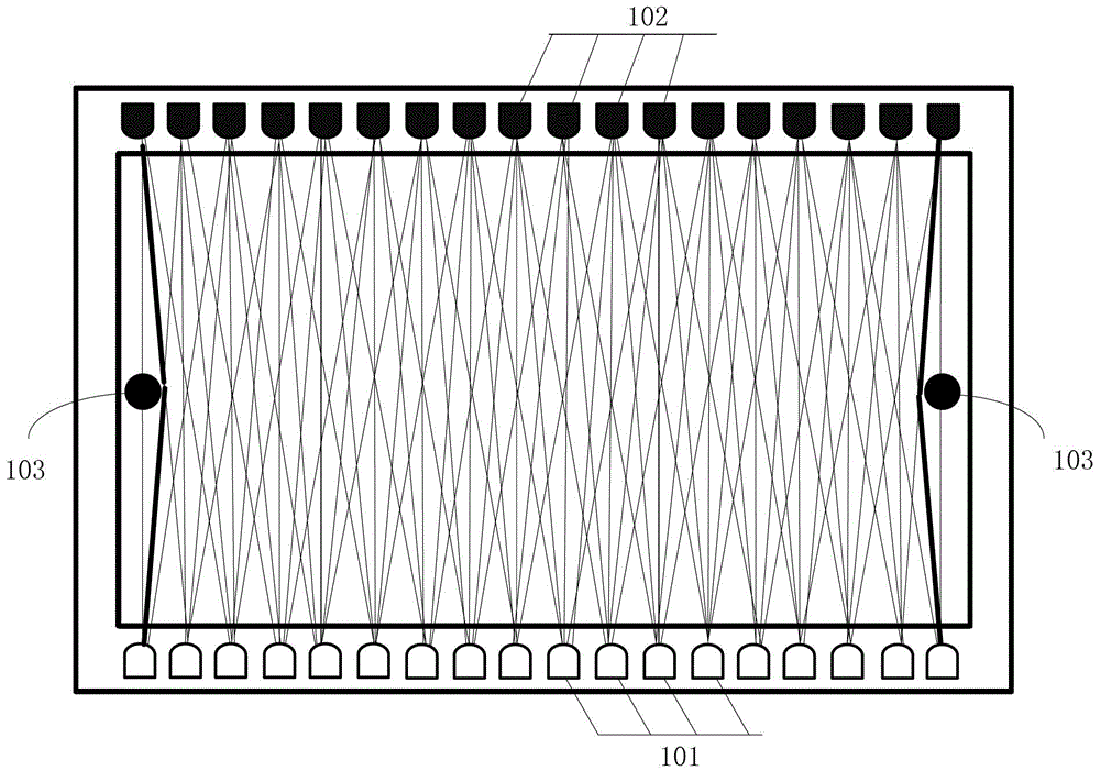
[0029] This embodiment provides an infrared touch screen, such as Figure 4As shown, it includes an infrared emitting element array 101 comprising a plurality of infrared emitting elements, an infrared receiving element array 102 comprising a plurality of infrared receiving elements and four edges, and these four edges are respectively a first edge 401 and a second edge 402, the third edge 403 and the fourth edge 404, wherein the first edge 401 is opposite to the third edge 402, the second edge 402 is opposite to the fourth edge 404, the infrared emitting element array 101 is installed on the first edge 401, and the infrared receiving The element array 102 is installed on the third edge 403, and the infrared light emitted by an infrared emitting element is received by at least one infrared receiving element on the opposite side, and a reflective element 405, 406 is respectively arranged on the second edge 402 and the fourth edge 404. The light beams emitted by the infrared emi...
Embodiment 2
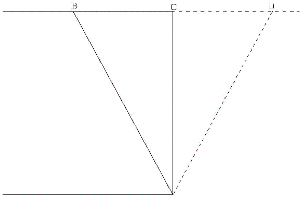
[0032] In order to prevent the signal crosstalk caused by the same infrared receiving element receiving the beam directly emitted by the same infrared emitting element and the beam reflected by the reflecting element after being directed to the reflecting element at the same time, that is to prevent a straight line of light and a broken line of light from simultaneously shooting to the same An infrared receiving element, in order to obtain a scanning line with a large inclination angle in the touch detection area, the infrared emitting element and the infrared receiving element can be installed at a certain angle, that is, the infrared emitting element and the infrared receiving element are connected to the first edge 401 or the first edge 401 The three edges 403 are not installed vertically, so that when the infrared receiving element is scanned, an infrared receiving element can only receive light beams from one direction at the same time. Such as Figure 5 As shown, it is a...
Embodiment 3
[0037] This embodiment provides a third infrared touch screen. This embodiment is the same as the first two embodiments, and the infrared emitting element and the infrared receiving element are respectively installed on the first edge and the third edge. A reflective element is installed. The difference between this embodiment and the previous two embodiments lies in the installation method of the infrared emitting element and the infrared receiving element.
[0038] In this example, if Figure 8 As shown, all the infrared emitting elements in the infrared emitting element array 101 are divided into a plurality of emitting groups 801 in sequence according to their positions, and each emitting group 801 includes three infrared emitting elements, wherein a vertical first edge 401 located in the middle is installed, located at The two on both sides are installed obliquely towards the second edge 402 (towards the right) and the fourth edge 403 (towards the left), so that there is ...
PUM
 Abstract
Description
Claims
Application Information