
Built-in electromagnetic heating roll

An electromagnetic heating roller and built-in technology, which is applied to the field of printing and dyeing rollers, can solve the problems of uneven surface temperature of the applicator roller, complex mechanical structure and high equipment cost, and achieve the effects of convenient construction, uniform temperature and low power consumption.

Inactive Publication Date: 2012-11-28
HANGZHOU ZHUODA ENERGY SAVING EQUIP
View PDF8 Cites 22 Cited by
  • Summary
  • Abstract
  • Description
  • Claims
  • Application Information

AI Technical Summary

Problems solved by technology

Its disadvantages are: the use of resistance wire or electric heating tube to heat the cloth roller has the problem that the surface temperature of the cloth roller is not uniform enough, and at the same time, the power consumption is large, and the heat energy is seriously wasted.
Use circulating steam to heat the applicator roller. Although the temperature on the surface of the roller is relatively uniform, the mechanical structure that needs to be designed for the circulating steam to be input into the roller is relatively complicated, which makes the equipment cost higher.

Method used


Image

  • Built-in electromagnetic heating roll
  • Built-in electromagnetic heating roll
  • Built-in electromagnetic heating roll

Examples


Embodiment Construction

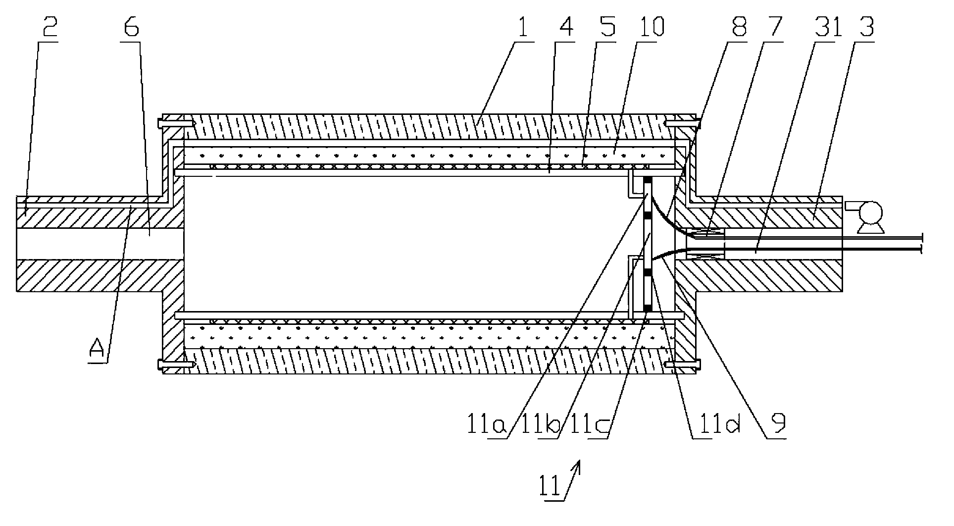
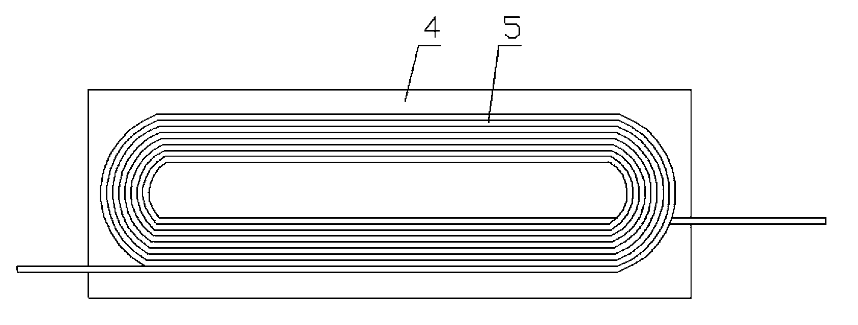
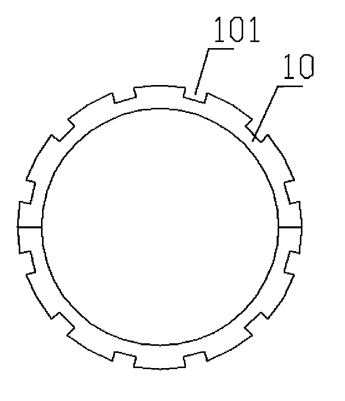
[0019] Example: see Figures 1 to 3 As shown, the built-in electromagnetic heating roller includes a roller 1, a left roller shaft 2 and a right roller shaft 3, and the two sides of the roller 1 are respectively fixed with a left roller shaft 2 and a right roller shaft 3 by screws, and a cylindrical substrate 4 An electromagnetic coil 5 is fixed on it, and the enameled wire terminals of the electromagnetic coil 5 protrude from the inner surface of the substrate 4 to be electrically connected with the positive connection plate 11a and the negative connection plate 11b on the power supply plate 11 respectively, and the positive connection plate 11a is fixed on the insulating outer ring 11c, the insulating outer ring 11c is fixed on the base plate 4, the insulating inner ring 11d is fixed on the inner ring of the positive contact plate 11a, the negative contact plate 11b is fixed on the insulating inner ring 11d, and the right roller shaft 3 is formed with a right The central thr...


PUM


Abstract

The invention discloses a built-in electromagnetic heating roll. An electromagnetic coil is fixed on a barrel-shaped substrate; the electromagnetic coil is electrified by a power supply plate; a right rotating connector is fixed in a central through hole of a right roll shaft; a positive wire and a negative wire of a power supply are fixed on the right rotating connector respectively; a positive elastic electric brush and a negative elastic electric brush are fixed on the right rotating connector; the positive elastic electric brush and the negative elastic electric brush are electrically connected with the positive wire and the negative wire of the power supply respectively; the positive elastic electric brush and the negative elastic electric brush are electrically in elastic contact with a positive contact plate and a negative contact plate respectively; two semicircular insulating heat-isolating bush sheets are buckled on the substrate and press the electromagnetic coil; ventilating slots are formed on the insulating heat-isolating bush sheets; the ventilating slots are communicated with ventilating passages which are formed on a left roll shaft and the right roll shaft; and the two ends of the substrate are fixed on the left roll shaft and the right roll shaft. The built-in electromagnetic heating roll is uniform in surface temperature, low in energy waste and low in electricity consumption.

Description

Technical field: [0001] The invention relates to the technical field of printing and dyeing rollers, in particular to a printing and dyeing roller or printing roller with built-in electromagnetic heating. Background technique: [0002] The existing dyeing rollers or printing rollers need to be heated in some occasions during actual work, so as to ensure the quality of dyeing and printing. For example, the flat screen printing machine needs to heat the cloth roller. Some manufacturers heat the cloth roller through resistance wire or electric heating tube, and some manufacturers heat the cloth roller through circulating steam. Its disadvantages are: the use of resistance wire or electric heating tube to heat the cloth applicator roller has the problem that the surface temperature of the cloth applicator roller is not uniform enough, and at the same time, the power consumption is large and the heat energy is wasted seriously. Although the temperature of the surface of the roll...

Claims


Application Information

Patent Timeline
Patent Type & Authority Applications(China)
IPC IPC(8): H05B6/14
Inventor 胡鑫
Owner HANGZHOU ZHUODA ENERGY SAVING EQUIP
Learn More