

Method and device for producing elongated metal components having helical grooves, especially twist drills or endless screws
A technology of auger bit and helical groove is applied in the manufacture of auger bit or screw, and the field of the device for implementing the method can achieve high cost performance.
- Summary
- Abstract
- Description
- Claims
- Application Information
AI Technical Summary
Problems solved by technology
Method used
Image

Examples
Embodiment Construction
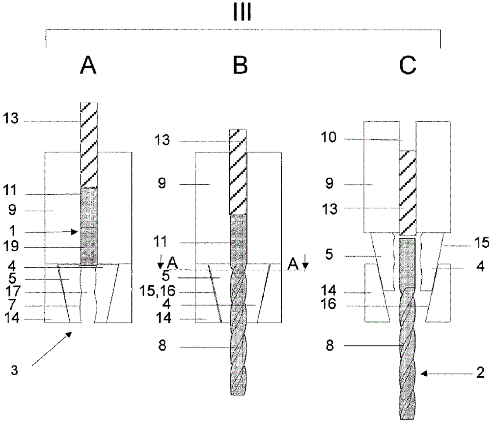
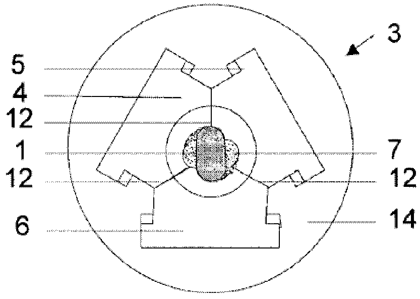
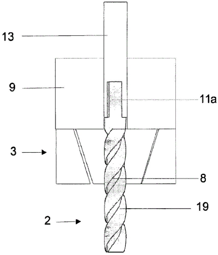
[0077] figure 1 The three steps A, B and C of the method according to the invention for producing an auger bit 2 from a blank 1 using a three-part split mold 3 are shown in a simplified manner. The three steps A, B and C constitute phase III of cold forming of the helical flutes 8 of the drill 2 . The blank 1 comprises a portion constituting the shank 11 and a portion 19 to be formed into a helical groove. The handle 1 can be designed, for example, as a cylindrical rod.
[0078] For the manufacture of the drill, a single die can be utilized, or the manufacturing process is done in a multi-stage punch press, where the blank 1 is also preformed from wire segments cut to specific lengths.
[0079] The multi-stage punching press, not shown in detail, comprises, in a structure known per se, a base frame with a movable carrier equipped with a die support unit. Furthermore, a shearing device, at least one extrusion or stamping die and a split die 3 are provided.
[0080] For stam...
PUM
 Abstract
Description
Claims
Application Information